Micro coaxial cable assembly having improved contacts

a technology of coaxial cable and contacts, applied in the manufacture of contact members, coupling device connections, coupling protective earth/shielding arrangements, etc., can solve problems affecting signal transmission, and achieve the effect of improving contacts

Inactive Publication Date: 2005-07-05
NEC LAB AMERICA +1
View PDF12 Cites 36 Cited by
  • Summary
  • Abstract
  • Description
  • Claims
  • Application Information

AI Technical Summary

Benefits of technology

[0006]Accordingly, one object of the present invention is to provide a micro coaxial cable assembly having improved contacts which can prevent from any flux contamination problem occurring.

Problems solved by technology

When the solid solder is heated, the solid solder is melted and the melted solder flows to the mating surface of the mating portion so that the mating surface of the contact is contaminated thereby influencing signal transmission.

Method used


Image

  • Micro coaxial cable assembly having improved contacts
  • Micro coaxial cable assembly having improved contacts
  • Micro coaxial cable assembly having improved contacts

Examples


Embodiment Construction

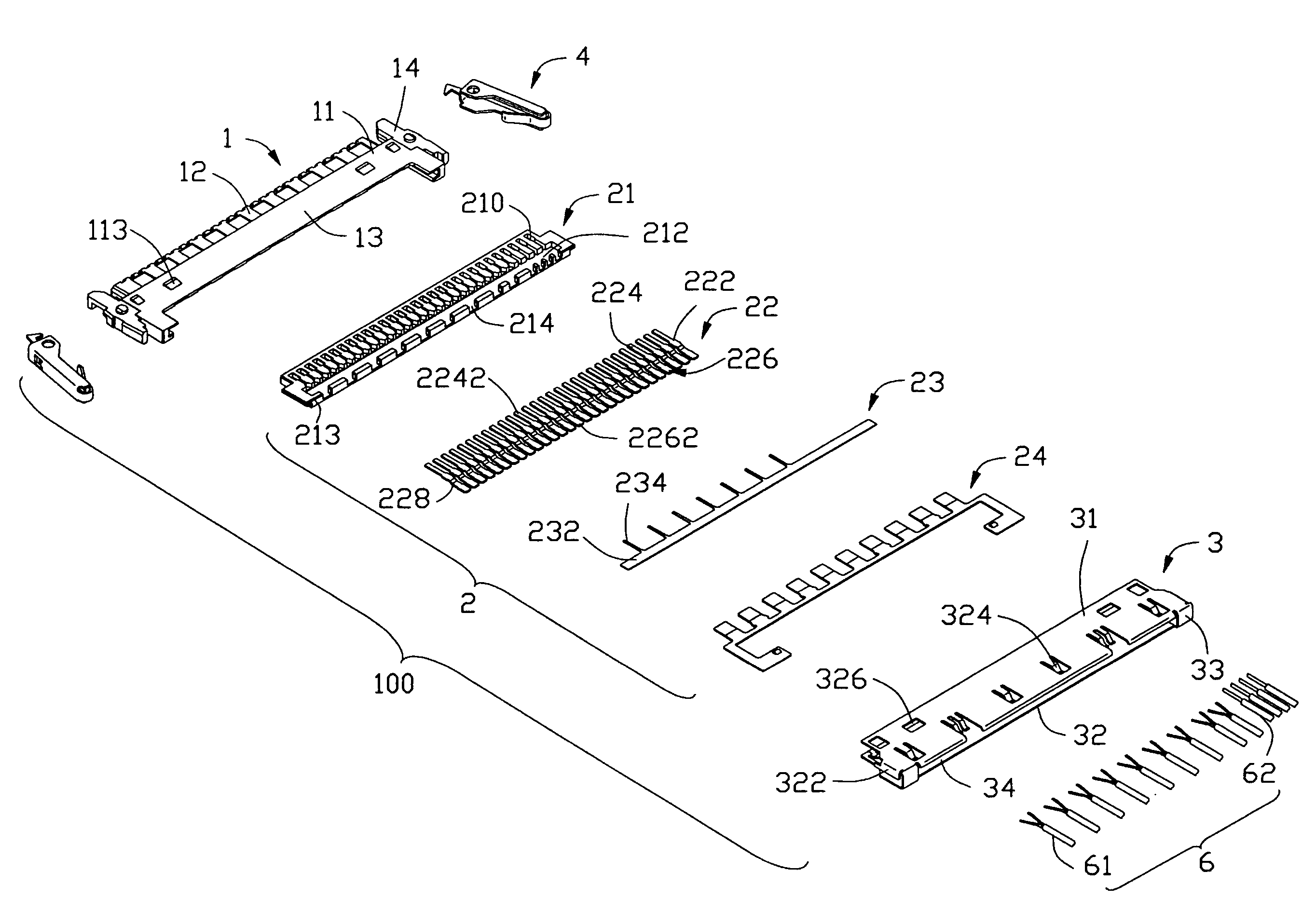
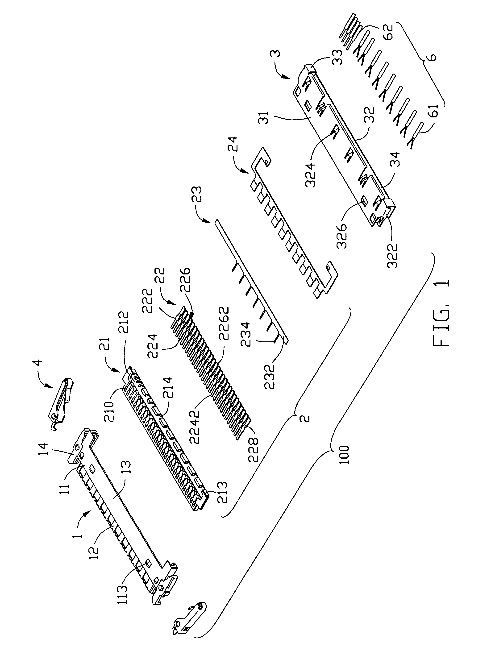
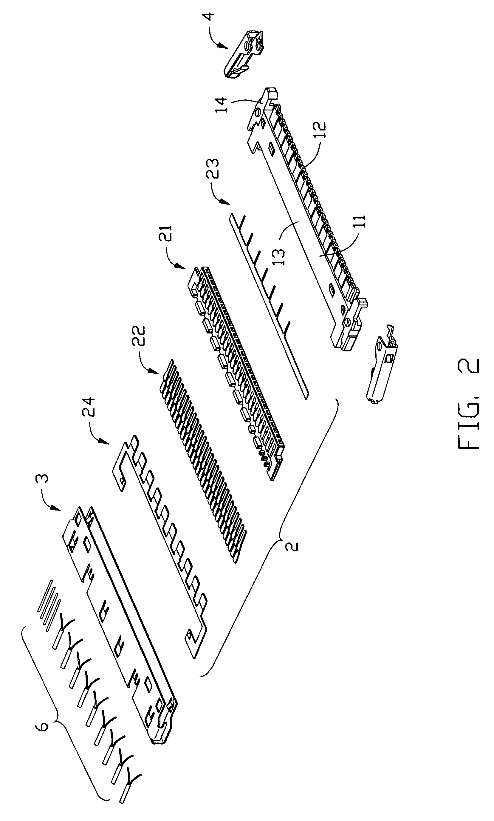
[0017]Referring to FIGS. 1–4, a micro coaxial cable assembly 100 of the present invention comprises an elongate insulative housing 1, a contact set 2, a shield 3, a pair of latch devices 4, and a plurality of cables 6.

[0018]The insulative housing 1 comprises an elongate base portion 11, a tongue portion 12 extending forwardly from the base portion 11, a rear portion 13 at a rear end of the base portion 11, and a pair of retention portions 14 formed on a pair of lateral ends of the base portion 11. The base portion 11 and the tongue portion 12 together define a plurality of passageways 111 from the rear end of the base portion 11 to a front end of the tongue portion 12. The rear portion 13 comprises an elongate plate 131 extending rearwardly from the base portion 11, a pair of receiving sections 132 formed on lateral ends of the elongate plate 131. Each of the receiving sections 132 defines a receiving channel 133 in an inner side thereof. A gap 15 is defined between each retention p...


PUM


Abstract

An electrical connector assembly (100) comprises an elongate insulative housing (1), a contact set (2), a shield (3), and a plurality of cables (6). The housing has a base portion (11) and a plurality of passageways (111) defined in the base portion. The contacts set is assembled into a rear end of the housing. The contact set comprises an insulative insert (21), a plurality of signal and grounding contacts (22) and a grounding bar (23) assembled in the insert. Each contact comprises a mating section (224) extending beyond the insulative insert and received into the corresponding passageways of the housing and a connecting section (226) remained in the insert, and a step section (228) between the mating section and the connecting section so that the mating section is not coplanar with the connecting section. The plurality of cables extends into the insulative insert and is electrically soldered to the connecting sections.

Description

CROSS-REFERENCE TO RELATED APPLICATION[0001]This patent application relates to two copending application Ser. Nos. 10 / 246,259 and 10 / 199,713.BACKGROUND OF THE INVENTION[0002]1. Field of the Invention[0003]The present invention relates to a micro coaxial cable assembly used in liquid crystal display (LCD) application, and particularly to such cable assembly having improved contacts.[0004]2. Description of Related Art[0005]U.S. Pat. Nos. 6,305,978 B1, 6,273,753 B1, 6,338,652 B1, D456,779 S, D456,780 S, D456,777 S, D457,138 S, and D444,130 S disclose low profiled micro coaxial cable connectors. This type connector is used to transmit signals between a mother board in a base of a notebook computer and an LCD panel of the notebook computer. In the old design, the micro coaxial cable connector assembly has the planar contacts and each contact comprises a mating portion and a soldering portion opposite to the mating portion. The soldering portion has a soldering surface and the mating port...

Claims


Application Information

Patent Timeline
Patent Type & Authority Patents(United States)
IPC IPC(8): H01R12/14H01R43/18H01R43/20H01R12/24H01R12/00H01R9/05H01R13/639H01R13/648H01R43/16
CPCH01R9/035H01R9/0512H01R12/592H01R13/6593H01R13/6583H01R13/65915
Inventor KO, DAVID TSO-CHIN
Owner NEC LAB AMERICA
Why Eureka
Try Eureka