Longitudinally flexible expandable stent

a flexible, long-term technology, applied in the field of endoprosthesis devices, can solve problems such as large gaps, improper vessel support, and vessel trauma

Inactive Publication Date: 2005-07-05
BOSTON SCI SCIMED INC
View PDF150 Cites 83 Cited by
  • Summary
  • Abstract
  • Description
  • Claims
  • Application Information

AI Technical Summary

Problems solved by technology

Unfortunately, a problem with such stents is that binding, overlapping or interference can occur between adjacent segments on the inside of a bend due to the segments moving toward each other and into contact or on the outside of a bend the segments can move away from each other, leaving large gaps.
This can lead to improper vessel support, vessel trauma, flow disturbance, kinking, balloon burst during expansion, and difficult recross for devices to be installed through already implanted devices and to unsupported regions of vessel.
A diamond configuration with diagonal connections between each and every diamond of each segment is also known but such closed configurations lack flexibility.

Method used


Image

  • Longitudinally flexible expandable stent
  • Longitudinally flexible expandable stent
  • Longitudinally flexible expandable stent

Examples


Embodiment Construction

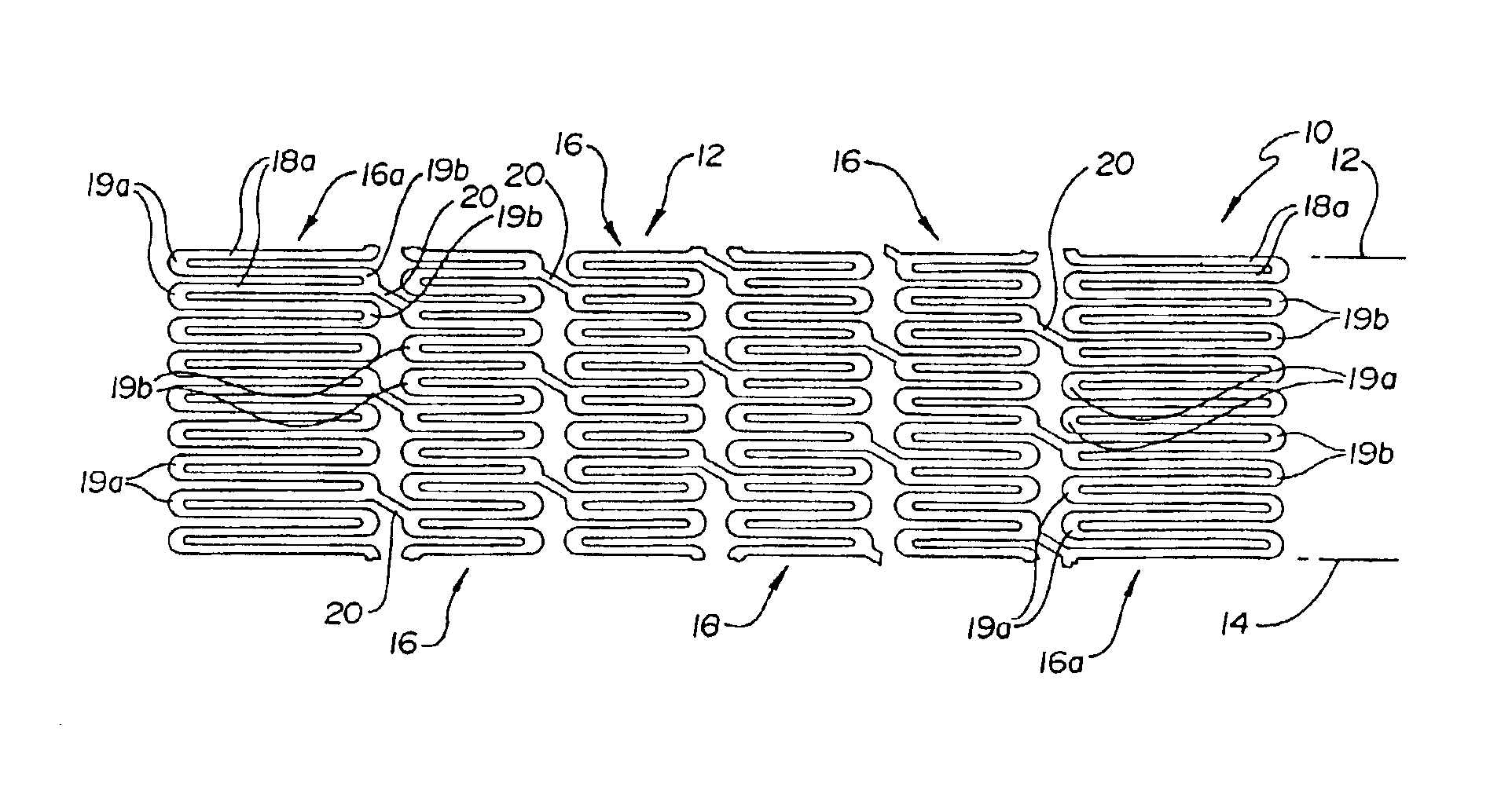
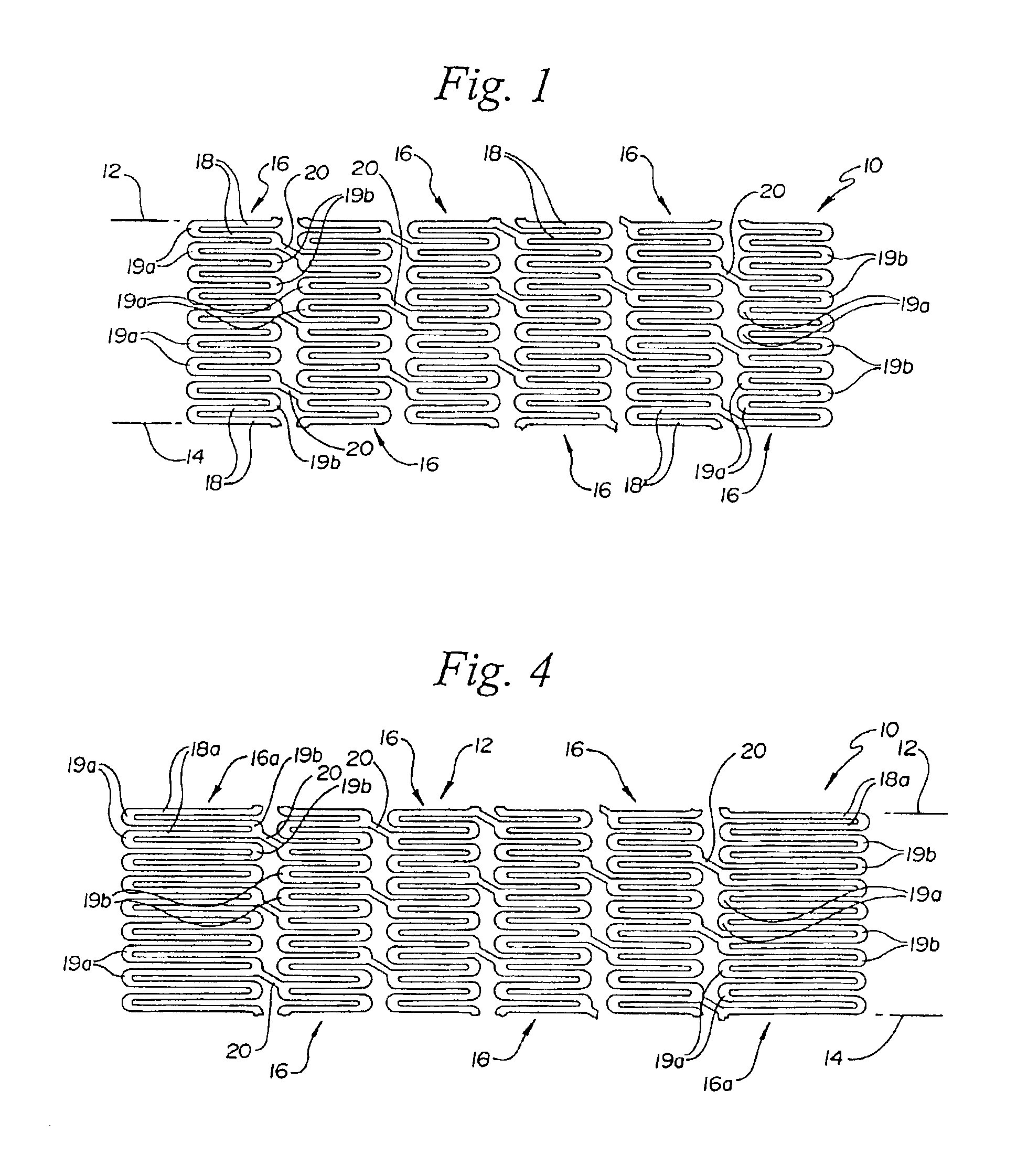
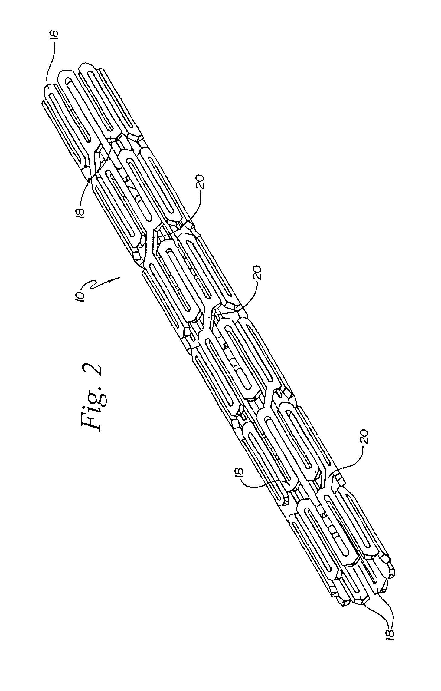
[0016]Turning to the Figures, FIG. 1 and FIG. 2 show a fragmentary flat view of an unexpanded stent configuration and the actual tubular stent (unexpanded), respectively. That is, the stent is shown for clarity in FIG. 1 in the flat and may be made from a flat pattern 10 (FIG. 1) which is formed into a tubular shape by rolling the pattern so as to bring edges 12 and 14 together (FIG. 1). The edges may then joined as by welding or the like to provide a configuration such as that shown in FIG. 2.

[0017]The configuration can be seen in these Figures to be made up of a plurality of adjacent segments generally indicated at 16, each of which is formed in an undulating flexible pattern of substantially parallel struts 18. Pairs of struts are interconnected at alternating end portions 19a and 19b. As is seen in FIG. 1, the interconnecting end portions 19b of one segment are positioned opposite interconnecting end portions 19a of adjacent segments. The end portions as shown are generally elli...


PUM


Abstract

A stent comprises a plurality of adjacent cylindrical elements defining a first end section, a second end section, and a center section therebetween. Each cylindrical element has constant thickness struts formed in a generally serpentine wave pattern transverse to the longitudinal axis which contains alternating valley portions and peak portions. A plurality of interconnecting members extend between the adjacent cylindrical elements and connect the adjacent cylindrical elements to one another. The cylindrical elements are formed of a stent material, the composition of which is uniform throughout the stent. The stent material of the struts in each of the first end section and the second end section have a greater mass than the stent material of the struts of the center section.

Description

[0001]This application is Continuation of application Ser. No. 08 / 511,076, filed Aug. 3, 1995, now U.S. Pat. No. 6,818,014, which is a Continuation-In-Part of application Ser. No. 08 / 396,569, filed Mar. 1, 1995, now abandoned, the disclosures of which are hereby incorporated by reference.FIELD OF THE INVENTION[0002]This invention relates to an endoprosthesis device for implantation within a body vessel, typically a blood vessel. More specifically, it relates to a tubular expandable stent of improved longitudinal flexibility.BACKGROUND OF THE INVENTION[0003]Stents are placed or implanted within a blood vessel for treating stenoses, strictures or aneurysms therein. They are implanted to reinforce collapsing, partially occluded, weakened, or dilated sections of a blood vessel. They have also been implanted in the urinary tract and in bile ducts.[0004]Typically, a stent will have an unexpanded (closed) diameter for placement and an expanded (opened) diameter after placement in the vesse...

Claims


Application Information

Patent Timeline
Patent Type & Authority Patents(United States)
IPC IPC(8): A61F2/06A61F2/00A61F2/915
CPCA61F2/91A61F2/915A61F2002/91525A61F2002/91533A61F2002/91541A61F2002/91558A61F2210/0019A61F2250/0018A61F2230/0054
Inventor BROWN, BRIAN J.DAVIS, MICHAEL L.
Owner BOSTON SCI SCIMED INC
Why Eureka
Try Eureka