
Visual display for vehicle

a visual display and vehicle technology, applied in the field of visual display, can solve the problem that the light does not convey information, and achieve the effect of reducing distraction

Inactive Publication Date: 2005-07-05
LEAR CORP
View PDF17 Cites 151 Cited by
  • Summary
  • Abstract
  • Description
  • Claims
  • Application Information

AI Technical Summary

Benefits of technology

The present invention is about a safety device for vehicles that uses a visual display system to communicate external or internal vehicular conditions and relative safety. The system includes a visual indicator with two different lighting characteristics that are actuated based on a signal received from a device that detects a vehicular condition. The goal is to minimize distraction for the driver and provide a more effective way of delivering external sensor data.

Problems solved by technology

The lights do not convey information of the severity of the problem causing the alert.

Method used


Image

  • Visual display for vehicle
  • Visual display for vehicle
  • Visual display for vehicle

Examples


Embodiment Construction

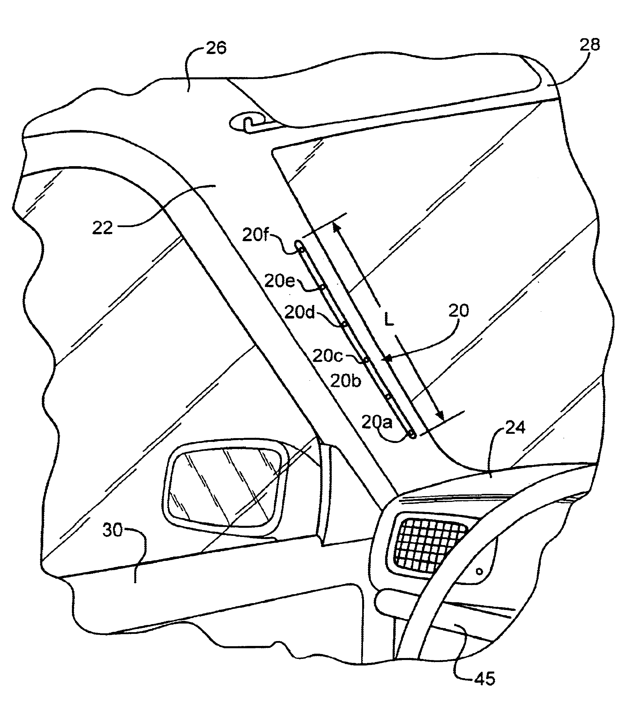
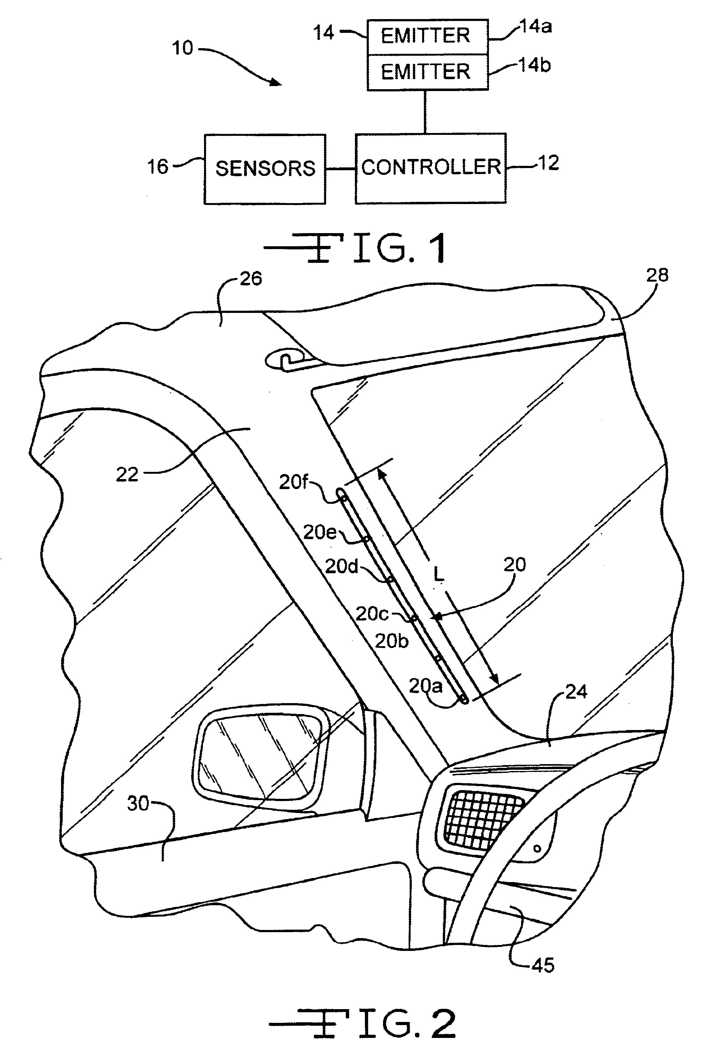
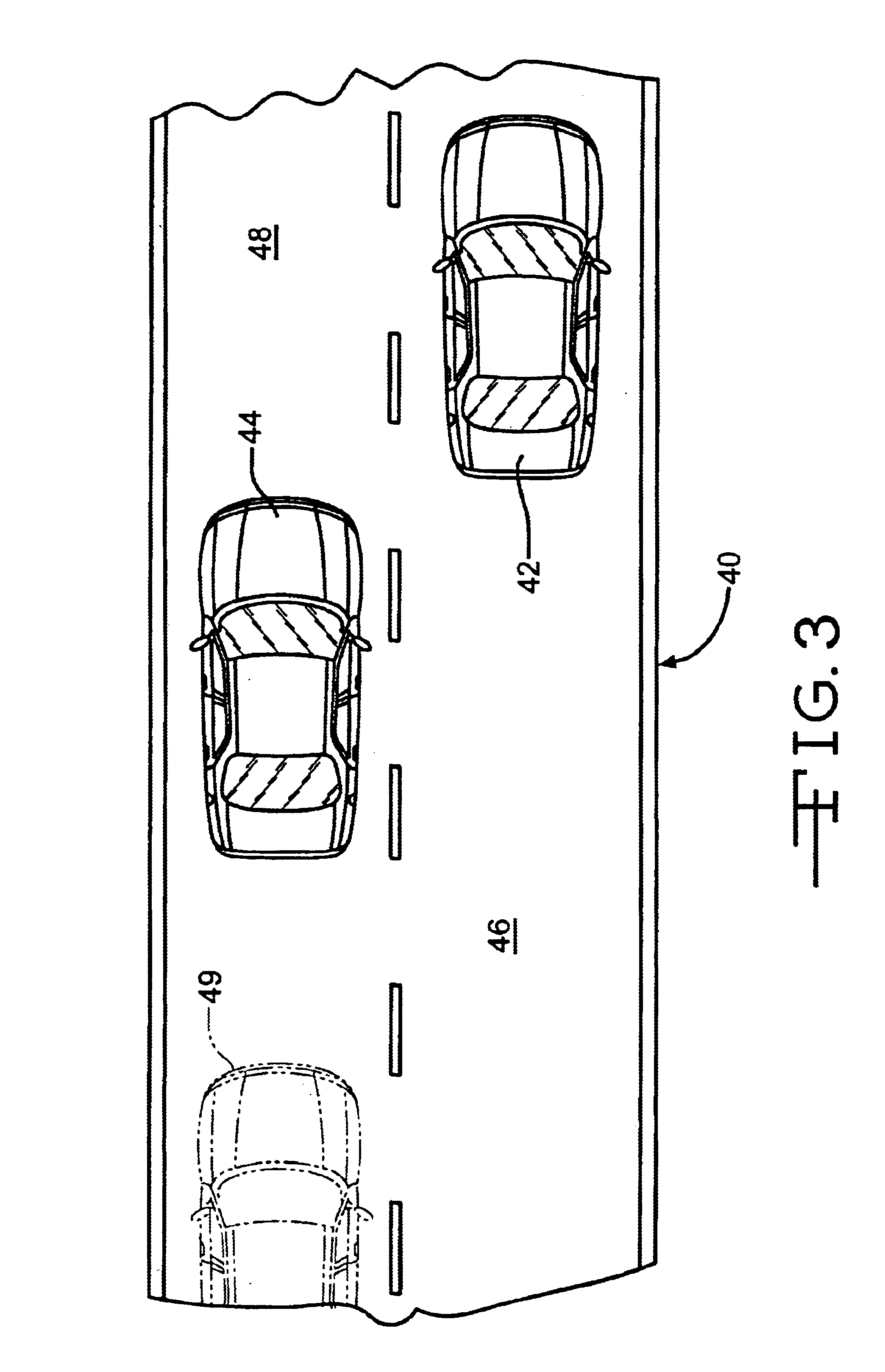
[0010]Referring now to the drawings, there is illustrated in FIG. 1 a schematic representation of a visual display system, indicated generally at 10, in accordance with the present invention. The display system 10 relates in generally to a visual method of delivering external sensor data to the driver in a manner which helps minimize distraction and communicates various internal or external vehicular conditions. In general, the system 10 includes a controller 12, a visual indicator assembly 14, and one or more devices or sensors 16. A suitable controller 12 would be a microprocessor which is connected to the sensor 16 receiving signals therefrom. The sensor 16 can be any suitable sensor device which detects a desired vehicular condition. Examples of detectable vehicular conditions include proximity detection, such as blind spot detection, impact detection, lane changing detection, reverse sensing, right angle sensing. Other examples include vehicle performance indicators such as tem...


PUM


Abstract

The visual display system of the present invention includes a visual indicator having at least first and second light emitters. A controller is connected to the visual indicator. The system further includes a device for detecting a vehicular condition and is capable of transmitting a signal to the controller in response to the vehicular condition. The controller is operable to actuate the first light emitter at a first lighting characteristic and the second light emitter at a second lighting characteristic different from the first lighting characteristic in response to the signal.

Description

CROSS REFERENCE TO RELATED APPLICATIONS[0001]This application claims the benefit of U.S. Provisional Application No. 60 / 372,539 filed Apr. 12, 2002.BACKGROUND OF THE INVENTION[0002]The present invention relates in generally to safety devices for vehicles. Most modern vehicles are equipped with various safety equipment to alert the driver of vehicular conditions and impending hazards. For example, some vehicles include warning lights or buzzers for alerting the driver of vehicle conditions such as low fuel, abnormal engine temperature, oil pressure, tire pressure, and abnormal readings from the vehicle's electrical charging system. The warning lights typically include a single light source which lights an indicator corresponding to the particular vehicle condition. Typically, these lights emit a single light source and are simply activated “on” to indicated a problem, or “off” to indicate that the condition is normal. The lights do not convey information of the severity of the proble...

Claims


Application Information

Patent Timeline
Patent Type & Authority Patents(United States)
IPC IPC(8): B60Q1/50B60Q9/00B60Q1/52
CPCB60Q9/008
Inventor ROTHKOP, JARON
Owner LEAR CORP
Learn More