Laser level

a laser level and laser technology, applied in the field of laser instruments, can solve the problems of considerable time saving of laser levels, and achieve the effect of improving laser levels

Inactive Publication Date: 2005-07-05
BLACK & DECKER INC
View PDF24 Cites 92 Cited by
  • Summary
  • Abstract
  • Description
  • Claims
  • Application Information

AI Technical Summary

Benefits of technology

[0005]In accordance with the present invention, an improved laser level is employed. The laser level disposable on a reference surface includes a housing, a pendulum pivotably connected to the housing, a first laser diode disposed on t...

Problems solved by technology

Laser levels save considerable time during initial layout of a construction...

Method used


Image

  • Laser level
  • Laser level
  • Laser level

Examples


Embodiment Construction

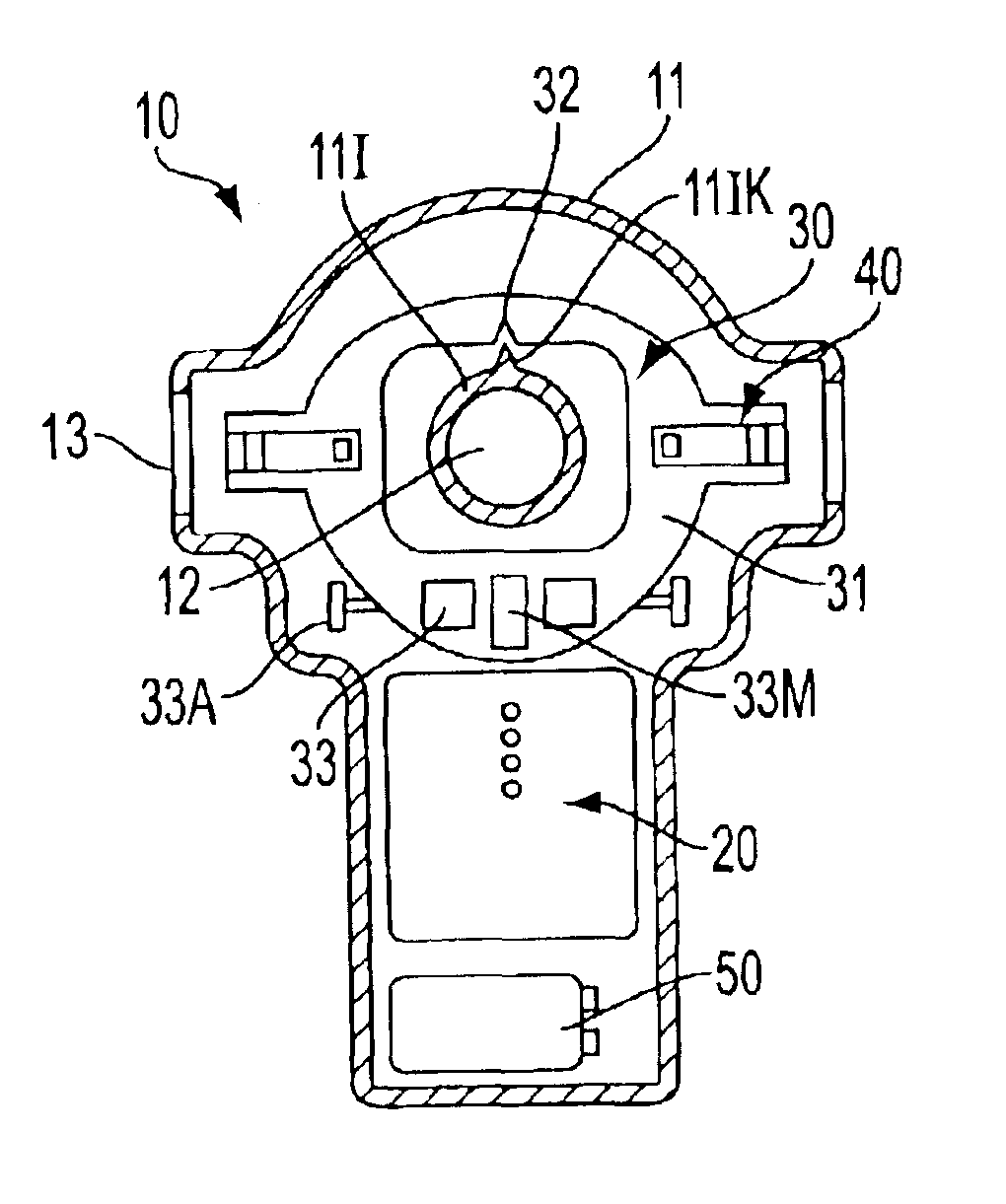
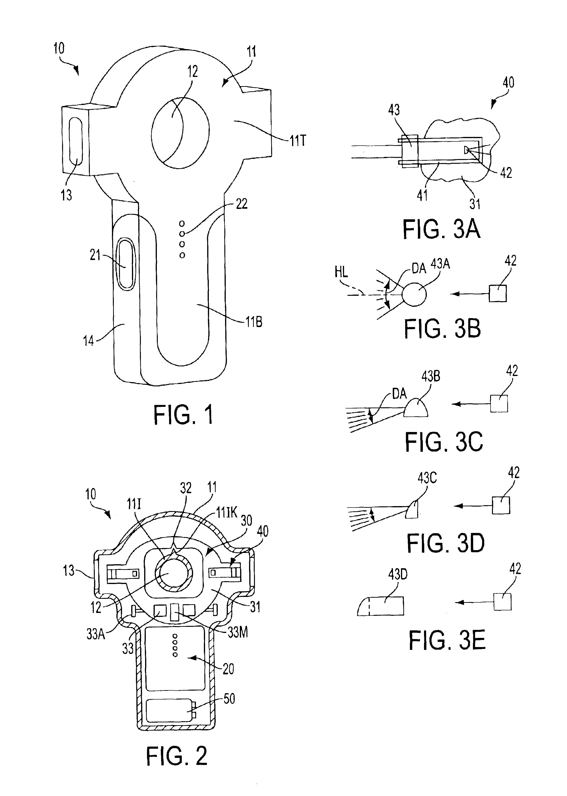
[0022]The invention is now described with reference to the accompanying figures, wherein like numerals designate like parts. Referring to FIGS. 1-2, a laser level 10 may have a housing 11. The housing 11 may have a top portion 11T and a bottom portion 11B. The housing may also have a hole 12 extending through the housing 11. The hole 12 preferably extends through the top portion 11T. The perimeter of the hole 12 may be defined by an inner wall 11I.

[0023]The top portion 11T may carry a pendulum assembly 30. Preferably, the pendulum assembly 30 has a main body 31, which may be made of metal or plastic. Main body 31 may be disposed on a knife edge 11IK at portion 32. Knife edge 11IK may be connected to and / or supported by inner wall 11I. Alternatively, knife edge 11IK maybe connected to and / or supported by housing 11. Persons skilled in the art will recognize that pendulum assembly 30 may be supported by means other than knife edge 11IK, such as a pin, bearing, point or other pendulous...


PUM


Abstract

A laser level disposable on a reference surface includes a housing, a pendulum pivotably connected to the housing, a first laser diode disposed on the pendulum for emitting a first laser beam along a first path, and a lens disposed on the pendulum in the first path for converting the first laser beam into a first planar beam, the first planar beam forming a line on the reference surface.

Description

CROSS-REFERENCE TO RELATED APPLICATIONS[0001]The present application claims priority under 35 USC § 119(e) of U.S. Application No. 60 / 384,673, filed on May 31, 2002, now pending.FIELD OF THE INVENTION[0002]This invention relates generally to laser instruments and specifically to laser levels.BACKGROUND OF THE INVENTION[0003]Laser levels have been used in construction for many years. They typically seek to produce a plane of light for a reference for construction projects. Laser levels have been used for large scale construction projects like commercial excavating, laying foundations, and installing drop ceilings. Laser levels save considerable time during initial layout of a construction job compared to other tools such as beam levels, chalk lines, or torpedo levels. Some examples of jobs where laser levels would be useful include laying tile, mounting cabinets, installing counter tops, and building outdoor decks.[0004]It is an object of the present invention to provide a laser leve...

Claims


Application Information

Patent Timeline
IPC IPC(8): G01C15/00G01C9/12G01C15/02
CPCG01C15/004G01C15/008Y10S33/21G01C15/00G01C15/10
Inventor RASKIN, JAMES R.COOPER, JEFFREY A.MARSHALL, JAMES D.SERGYEYENKO, OLEKSIY P.WHEELER, THOMAS J.
Owner BLACK & DECKER INC
Why Eureka
Try Eureka