
Laser noise elimination circuit and optical disc device

a laser noise and optical disc technology, applied in the direction of optical beam sources, instruments, record information storage, etc., can solve the problems of affecting the signal reproduced from the optical disc, servo signal components, and components close to dc, so as to reduce the output level of the laser beam source, efficiently and effectively eliminate the laser noise, and raise the level of the laser noise contained

Inactive Publication Date: 2005-06-23
SONY CORP
View PDF6 Cites 3 Cited by
  • Summary
  • Abstract
  • Description
  • Claims
  • Application Information

AI Technical Summary

Benefits of technology

[0009] In view of the above identified circumstances, it is therefore an object of the present invention to provide a laser noise elimination circuit that can eliminate only the laser noise component from a highly accurate APC signal and an RF signal by raising the gain of the APC signal in a data reproducing operation and prevent the circuit from being saturated in a data writing operation so as to make the APC operate smoothly and also an optical disc device comprising such a laser noise elimination circuit.
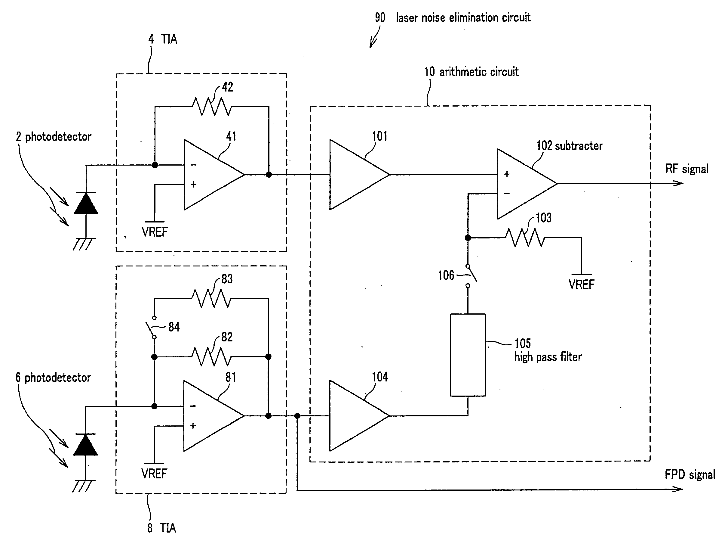
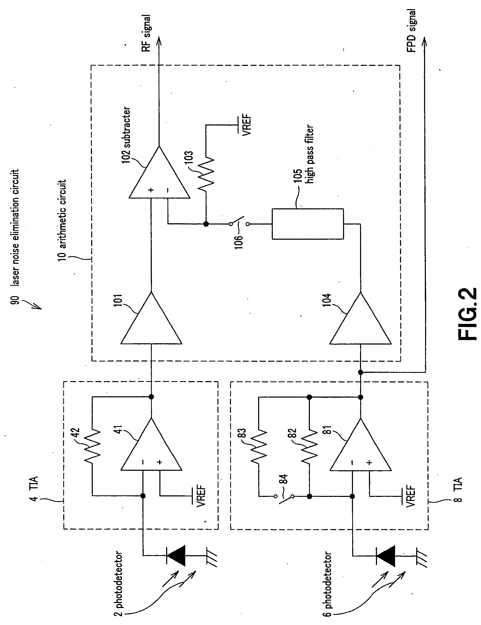
[0012] With a laser noise elimination circuit and an optical disc device comprising such a circuit according to the invention, reflected light of a laser beam from the optical disc mounted in the optical disc device is modulated by the recorded signal of the optical disc and carries a laser noise. Therefore, the first signal, or the RF signal, obtained by photoelectric conversion of the reflected light contains the laser noise. On the other hand, the second signal, or the FPD signal, obtained by photoelectric conversion of part of the laser beam also contains the laser noise as well as a DC component. Thus, only the laser noise is extracted by cutting out the DC component from the FPD signal by the filter means so that it is possible to obtain an RF signal in which the laser noise is reduced and the DC component is not cut out by subtracting the laser noise from the RF signal. It is possible to raise the level of the laser noise contained in the second signal, or the FPD signal, to make it flush with the laser noise contained in the RF signal by raising the gain of the second photoelectric conversion means in a reproduction mode of the optical disc device when the output level of the laser beam source is reduced. Therefore, it is possible to efficiently and effectively eliminate the laser noise from the RF signal and, at the same time, raise the level of the FPD output that falls in a reproduction mode of the optical disc device so as to make the APC operation highly accurate. Additionally, the amplitude level of the second signal, or the FPD signal, is prevented from rising too high so that consequently the circuit is prevented from being saturated and a smooth APC operation can be realized by reducing the gain of the second photoelectric conversion means in a write mode for writing data onto the optical disc when the output level of the laser beam source rises.
[0013] Thus, according to the present invention, it is possible to always effectively eliminate the laser noise from the RF signal and, at the same time, raise the FPD output level that falls in a reproduction mode by cutting out the DC component of the FPD signal that is obtained by photoelectric conversion of part of the laser beam and subtracting the FPD signal from the RF signal obtained by photoelectric conversion of reflected light from the optical disc of the laser beam emitted from a laser beam source and by raising the gain when the laser beam is partly subjected to photoelectric conversion in a write mode of the optical disc device for writing data onto the optical disc when the output level of the laser beam source falls. Then, a highly accurate APC operation can be realized.
[0014] Additionally, the FPD circuit can be prevented from being saturated by reducing the gain of the second photoelectric conversion means in a write mode for writing data onto the optical disc when the output level of the laser beam source rises because the amplitude level of the second signal, or the FPD signal, does not rise too high. Then, a highly smooth APC operation can be realized.

Problems solved by technology

However, the signal reproduced from the optical disc is adversely affected by laser noises, which are boosted by return light from the optical disc and / or temperature changes.
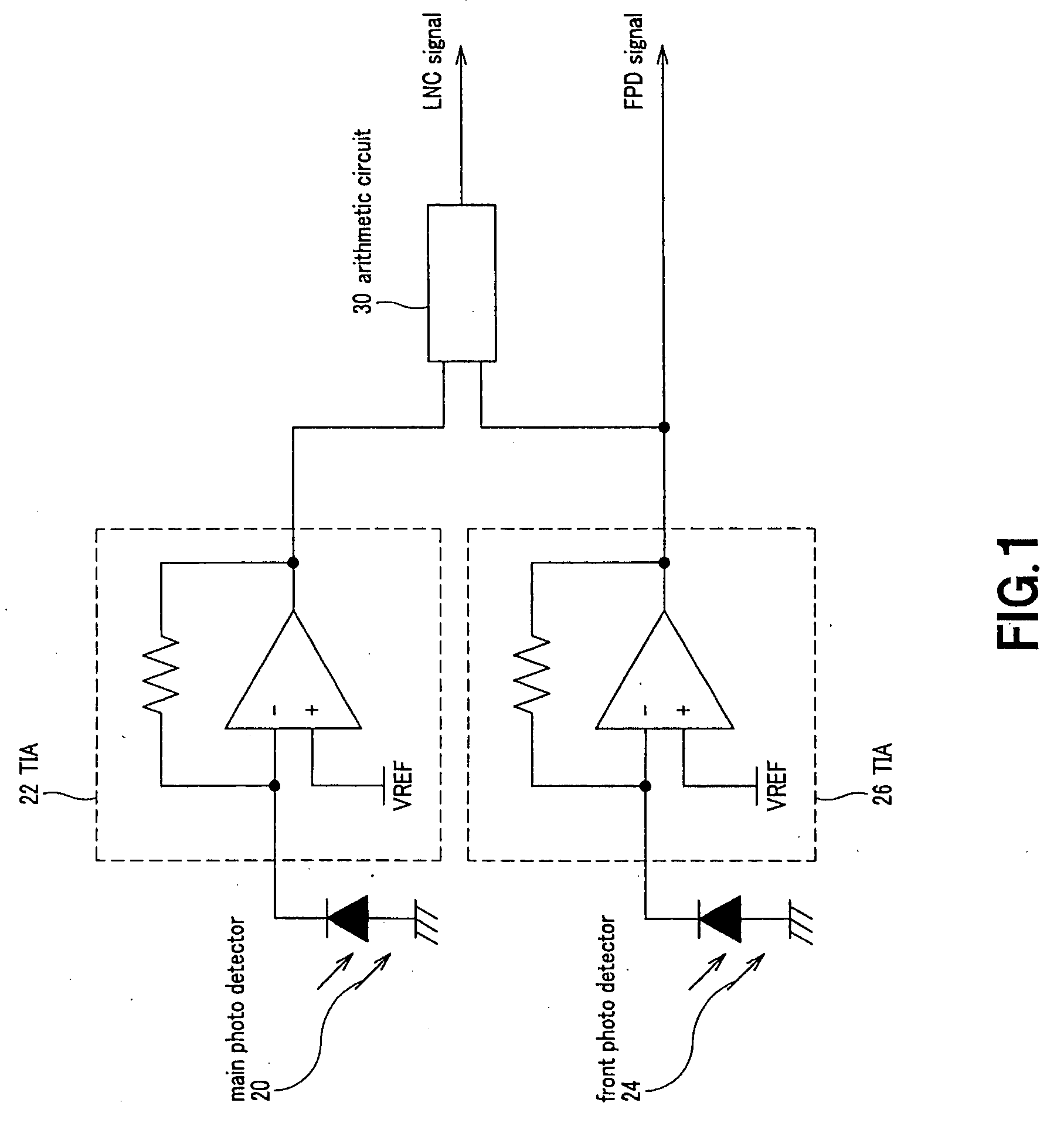
However, while the laser noise is reduced by the above described known laser noise canceling method, the servo signal component that is constituted by a component close to DC is affected to give rise to a problem of difficulty of accurately operating the servomechanism, because a direct current (DC) component is also subtracted from the RF signal when the FPD signal is subtracted from the RF signal.
Then, the APC operation becomes difficult and, at the same time, the laser noise contained in the FPD signal and the circuit noise of the photo detector and that of the TIA circuit and other circuits show substantially the same level, depending on the circumstances, in the laser noise eliminating operation that is conducted in a data read mode.

Method used


Image

  • Laser noise elimination circuit and optical disc device
  • Laser noise elimination circuit and optical disc device
  • Laser noise elimination circuit and optical disc device

Examples


first embodiment

[First Embodiment]

[0021]FIG. 2 is a schematic circuit diagram of the first embodiment of laser noise elimination circuit according to the invention, illustrating the configuration thereof. Referring to FIG. 2, laser noise elimination circuit 90 comprises a photo detector 2 for receiving reflected light of the laser beam emitted from a laser beam source (not shown) for a semiconductor laser and the like and irradiated onto an optical disc (not shown) for photoelectric conversion, a TIA 4 for converting the electric current signal output from the photo detector 2 into a voltage signal, a photo detector 6 for receiving part of the laser beam emitted from the laser beam source for photoelectric conversion, a TIA 8 for converting the electric current signal output from the photo detector 6 into a voltage signal and an arithmetic circuit 10 for eliminating the laser noise component contained in the RF signal input from the TIA 4 by means of the RF signal and the FPD signal input from the ...

second embodiment

[Second Embodiment]

[0030]FIG. 3 is a schematic circuit diagram of the second embodiment of laser noise elimination circuit according to the invention, illustrating the configuration thereof. Note that the components same as those of the first embodiment of FIG. 2 are denoted respectively by the same reference symbols and will not be described any further. While a laser noise elimination circuit 90′ of this embodiment operates same as the first embodiment and provides advantages similar to those of the first embodiment, its configuration slightly differs from the first embodiment. While the TIA 14 of the laser noise elimination circuit 90′ of this embodiment is made to show a fixed gain, the laser noise elimination circuit 90′ comprises two signal routes for transmitting the FPD signal output from the TIA 14 including one for transmitting the signal to high pass filter 105 and then to the subtracter 102 and also to a changeover switch 113 by way of an amplifier 110 showing a high gai...

third embodiment

[Third Embodiment]

[0033]FIG. 4 is a schematic circuit diagram of the third embodiment of laser noise elimination circuit according to the invention, illustrating the configuration thereof. Note that the components same as those of the first embodiment of FIG. 2 are denoted respectively by the same reference symbols and will not be described any further. The arithmetic circuit 10 may be made free from a high pass filter as in the case of the laser noise elimination circuit 91 of this embodiment depending on the accuracy of servo operation of the optical pickup.

[0034] In this embodiment, the noise level of the FPD signal is made to match that of the RF signal at the input section of the arithmetic circuit 10 so as to obtain a signal showing a high power level in a reproduction mode where the laser power is low and facilitate the APC control operation by raising the gain of the TIA 8 and hence the level of the FPD signal in a reproduction mode. Additionally, the FPD circuit is prevent...


PUM

PropertyMeasurementUnit
photoelectricaaaaaaaaaa
photoelectric conversionaaaaaaaaaa
currentaaaaaaaaaa

Abstract

A laser noise elimination circuit raises the gain of a first TIA and at the same time reflected light from an optical disc of a laser beam is subjected to photoelectric conversion by means of a photo detector and a second TIA to obtain an RF signal. Then, the direct current component of the FPD signal obtained by photoelectric conversion of part of the laser beam by means of another photo detector and the first TIA is cut out by a high pass filter and then subtracted by a subtracter. The gain of the first TIA is raised in a read mode of operation for reading data from the optical disc and lowered in a write mode of operation for writing data onto the optical disc so as to always effectively eliminate only the laser noise from the RF signal and prevent the circuit from being saturated in a write mode.

Description

BACKGROUND OF THE INVENTION [0001] 1. Field of the Invention [0002] This invention relates to an optical disc device for reading data from and writing data to an optical disc and also to a laser noise elimination circuit for reducing laser noises. [0003] 2. Description of Related Art [0004] Optical disc devices read / write data by irradiating a laser beam emitted from a semiconductor laser onto the surface of an optical disc. However, the signal reproduced from the optical disc is adversely affected by laser noises, which are boosted by return light from the optical disc and / or temperature changes. An LNC (laser noise canceling) method is known as laser noise reduction method for offsetting the laser noise component by subtracting the monitor output signal for APC (automatic power control) from the reproduced RF signal (see, inter alia, Patent Document 1: Japanese Patent Application Laid-Open Publication No. 10-124919). [0005] Referring to FIG. 1 of the accompanying drawings, return ...

Claims


Application Information

Patent Timeline
Patent Type & Authority Applications(United States)
IPC IPC(8): G11B7/005G11B7/00G11B7/125G11B7/1263G11B7/135G11B20/02
CPCG11B7/1263G11B7/126
Inventor FUKUTOMI, YOSHIONAGARA, TORU
Owner SONY CORP
Learn More