Sanitary tub

a technology for tubs and sanitary tubs, applied in the field of sanitary tubs, can solve the problems of accessories, soap dishes, and inability to move around the tub body, and achieve the effect of avoiding the need for movable attachment of accessories to the tub body, and ensuring the safety of the patien

Inactive Publication Date: 2005-07-12
ANDREJEWSKI HONKE & SOZIEN +1
View PDF5 Cites 47 Cited by
  • Summary
  • Abstract
  • Description
  • Claims
  • Application Information

AI Technical Summary

Benefits of technology

[0011]In another embodiment, the carrier for the tub edge covering forms an installation space for electrical installations and / or water installations, and functional elements of these installations are arranged on the bottom edge of the carrier. Because of their installation within the groove, the functional elements are arranged so that they are covered to a great extent. Cleaning jets or jets for feeding liquid bath substances, which are connected with lines for liquid in the installation space of the carrier, can be arranged on the bottom edge of the carrier. Furthermore, a device for illuminating the tub interior may be housed in the installation space of the carrier. The arrangement can easily be made in such a manner that the light exits from the groove that is open towards the tub interior as a band of light.

Problems solved by technology

In the case of conventional tub bodies, there is the problem that bath furniture cannot be suspended in the tub body, and accessories, for example soap dishes, cannot be attached to the tub body in movable manner.

Method used


Image

  • Sanitary tub
  • Sanitary tub
  • Sanitary tub

Examples


Embodiment Construction

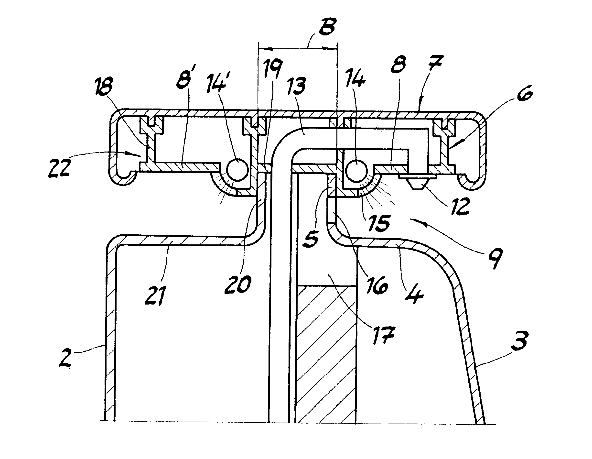
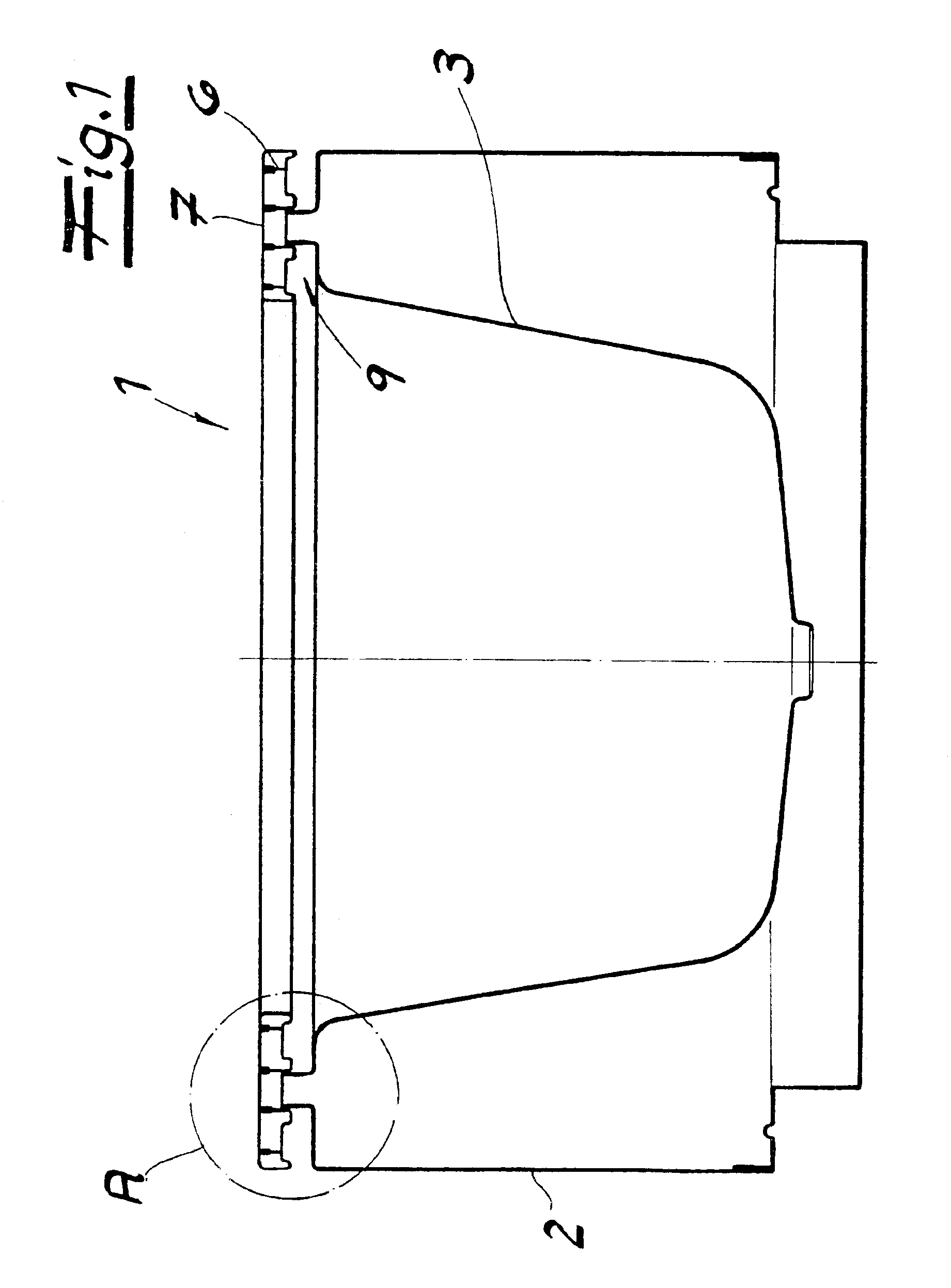
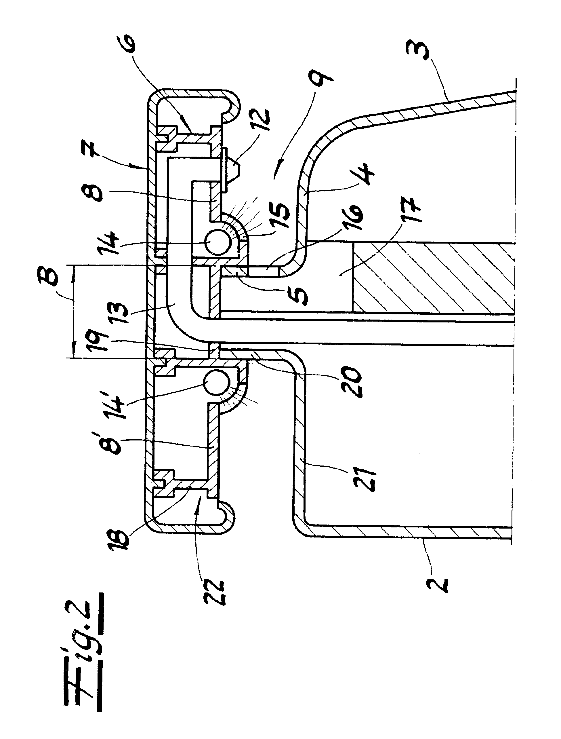
[0021]Turning now in detail to the drawings, FIG. 1 shows the outlines of a sanitary tub 1 having a tub paneling 2. As shown in FIG. 2, the sanitary tub 1 consists of a tub body 3 having a tub edge 4 that is turned towards the outside, which ends with an up-drawn collar 5 on the circumference. A carrier 6 having a tub edge covering 7, which can be variably structured with regard to material, color, and design, is attached to the collar 5.

[0022]Plastic or metal profiles, wood profile strips, elastically resilient molded bodies or, if applicable, natural stone elements can be used as the tub covering 7. The carrier 6 has a bottom edge 8 arranged at a distance above the tub edge 4 which, together with tub edge 4, forms a groove 9 that is open towards the interior of the tub body. Groove 9 can be used for hanging bath furniture 10, as shown as an example in FIG. 4. The bath furniture 10 has guide tabs 11 that engage in the groove 9 between the carrier 6 and the tub edge 4.

[0023]As shown...


PUM


Abstract

A sanitary tub has a tub body with a tub edge on the perimeter of the tub body that has been turned towards the outside. The tub edge has a substantially vertical collar on its circumference. A carrier secured to a tub edge covering is attached to the collar. The carrier has a bottom edge arranged at a distance above the tub edge which, together with the tub edge, form a groove that is open towards the interior of the tub body.

Description

CROSS REFERENCE TO RELATED APPLICATIONS[0001]Applicant claims priority under 35 U.S.C. §119 of German Patent Application No. 102 54 004.7 filed Nov. 19, 2002.BACKGROUND OF THE INVENTION[0002]1. Field of the Invention[0003]The invention relates to a sanitary tub having a tub body with a tub edge that has been turned towards the outside, whereby the tub edge ends with an up-drawn collar. The tub body consists, for example, of enameled sheet steel, a deep-drawn plastic shell, or a laminate material having an outer shell made of sheet steel and an inner shell of plastic. Within the scope of the invention, tub bodies having a high level of shape rigidity are preferred.[0004]2. Prior Art[0005]A sanitary tub having the characteristics described initially is known from DE 298 19 364 U1. The up-drawn collar of the tub edge lies against a wall surface, interposed by a seal. The wall surface is tiled above the tub edge, whereby the first row of tiles lies against the outside of the seal arrang...

Claims


Application Information

Patent Timeline
Patent Type & Authority Patents(United States)
IPC IPC(8): A47K3/00A47K3/02E03C1/12E03C1/14F21V33/00
CPCA47K3/001E03C1/14A47K3/02F21V33/004
Inventor SIEGER, CHRISTIANSIEGER, MICHAEL
Owner ANDREJEWSKI HONKE & SOZIEN
Why Eureka
Try Eureka