Resilient, all-surface soles for footwear

a technology of all-surface soles and soles, which is applied in the direction of uppers, bootlegs, stiffners, etc., can solve the problems ofsoles not having uniform resilience or density

Inactive Publication Date: 2005-07-12
KASTNER
View PDF12 Cites 65 Cited by
  • Summary
  • Abstract
  • Description
  • Claims
  • Application Information

AI Technical Summary

Benefits of technology

[0010]In one specific embodiment the sole is formed so that the resilience thereof varies between the bottom and upper surfaces of the sole. Such variation can be uniform, that is, more resilient at the bottom, work-contacting surface of the sole and least resilient at the portion of the sole that contact the shoe upper. In another embodiment the sole is formed from layers of rubber, a more resilient zone being located at the bottom of the sole even at the uppermost zone, with a less resilient, i.e., harder zone being formed at a central location to lend stability to the shoe. Yet in another embodiment the more resilient zone can be located between the two, harder zones of rubber. It is in this softer zone of rubber that the anchoring portion of a stud is located; in this manner an easily retractable stud is formed although the work contacting surface of the sole is relatively hard, so that the sole may be worn on a hard, indoor surface without unduly scuffing it.
[0012]With respect to processes for the manufacture of soles that have varying degrees of resilience through their depths, the soles can be formed in a single molding operation in which the resilient material, such as natural or synthetic rubber, has its composition varied from one surface of the sheet from which the soles are formed to the other surface. Alternatively, the sole can be molded from individual sheets. For example, two sheets of less resilient and one sheet or more resilient can be formed and cut to size, and the more resilient layer sandwiched between the harder layers and molded to them. Production efficiencies may determine which methods of forming the desired structures prove more effective.

Problems solved by technology

This requires that the sole not have a uniform resilience or density, because it is not formed from rubber or other material that is uniformly resilient.

Method used


Image

  • Resilient, all-surface soles for footwear
  • Resilient, all-surface soles for footwear
  • Resilient, all-surface soles for footwear

Examples


Embodiment Construction

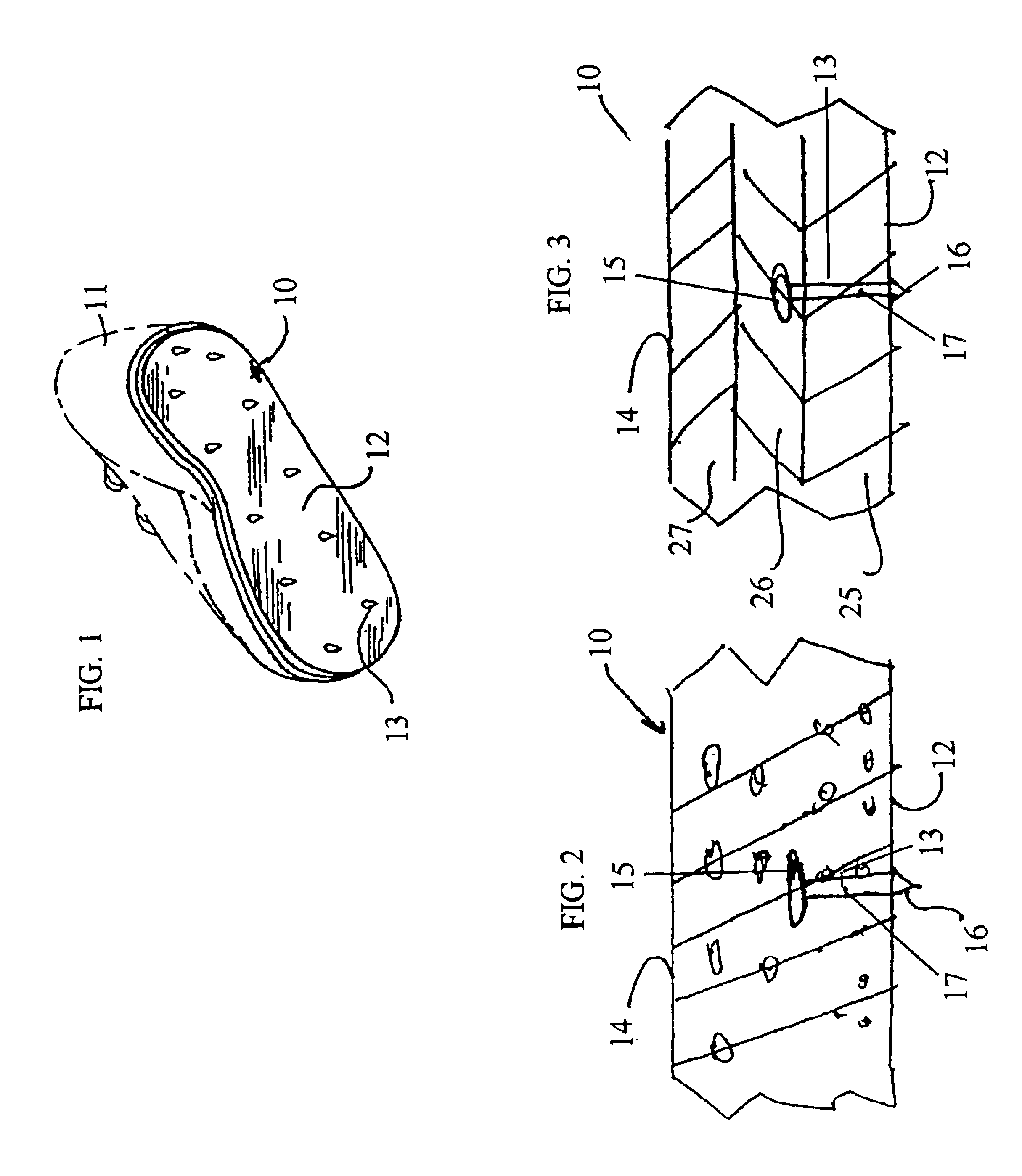
[0020]Referring now to the drawings, and in particular to FIG. 1 thereof, what is shown in an all-surface sold 10 in place on footwear 11. Sole 10 may be permanently attached to shoe 11 or may be removable therefrom and placed, either with another, similar sole after excessive wear, or with another sole that has different characteristics.

[0021]As generally shown, sole 10 has a bottom, work-contacting surface 12, from which protrude a plurality of metal studs 13. The upper surface 14 of the sole is not seen in FIG. 1, but lies in juxtaposition to the upper of the shoe 11. The pattern in which the studs 13 are arranged is predetermined and is not considered to be part of the present invention.

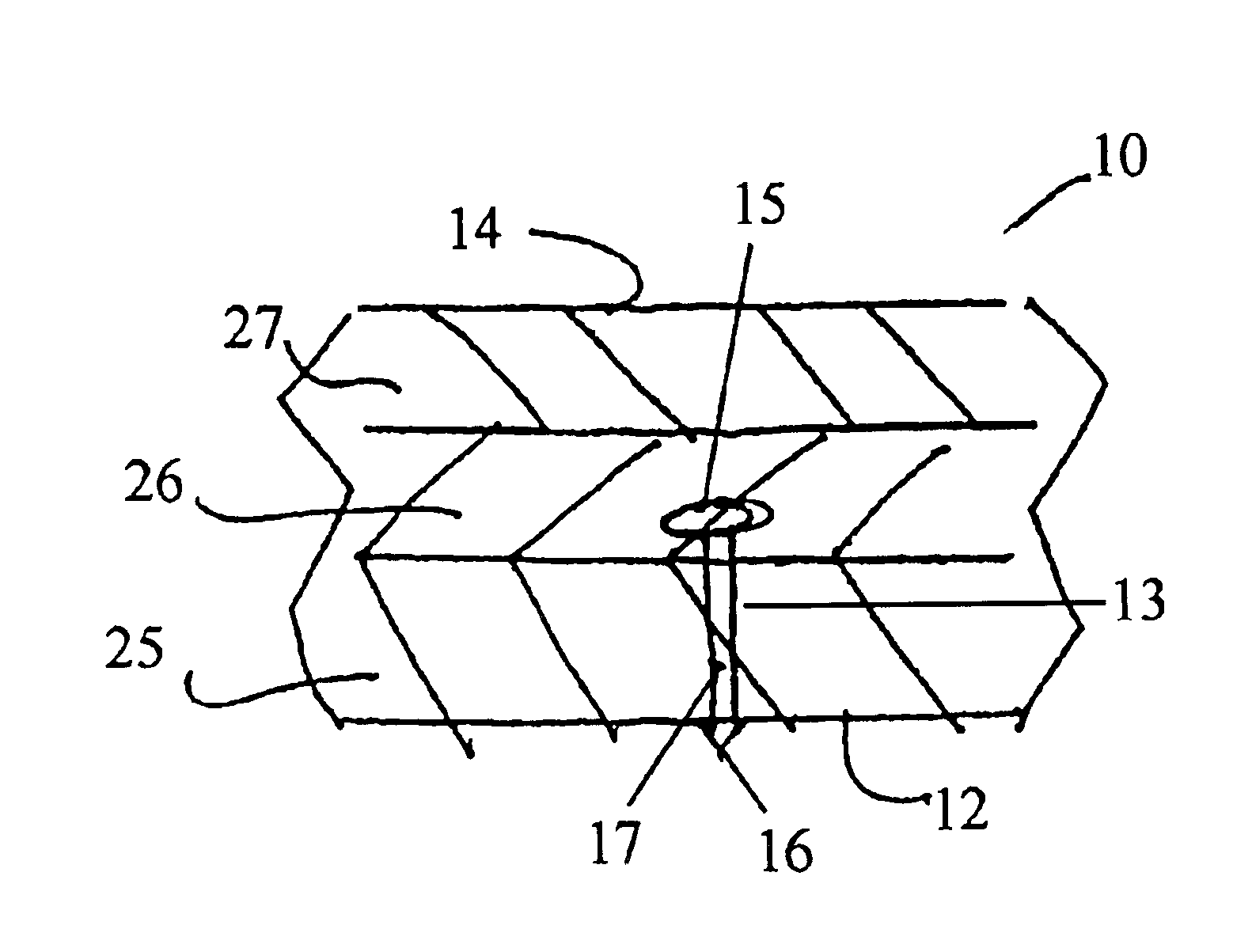
[0022]The structure of a stud 13, which is preferably made of metal, is best seen in FIGS. 2 and 3. As is the case with the studs of my U.S. Pat. No. 5,634,283, each stud 13 is formed with an anchoring portion 15, a tip portio 16, and a cylindrical or conical shank or shaft portion 17 so that it ...


PUM


Abstract

A resilient shoe sole having a less resilient outer layer and a more resilient inner layer, and retractable studs anchored in the inner, more resilient layer. The bottom surface of the sole has annular grooves formed around the tip portions of the studs to permit those portions to flex when pressure is applied to the bottom surface, as during walking on a hard surface.

Description

[0001]This application is a continuation of Ser. No. 09 / 948,597 filed on Sep. 10, 2001 now abandoned.FIELD OF THE INVENTION[0002]The present invention relates to improvements in resilient, all-surface soles that are applied to or or are integral part of footwear. More specifically, it relates to improvements in such soles as described, illustrated and claimed in my U.S. Pat. No. 5,634,283, which was issued on Jun. 3, 1997.BACKGROUND OF THE INVENTION[0003]As more fully disclosed in U.S. Pat. No. 5,634,283, on which I am the named inventor and the disclosure of which is hereby fully incorporated herein by referende, it has long been a challenge to those of skill in the art of designing footwear to devise footwear having soles that enable the wearer to have traction on surfaces that may be classified as slippery, e.g., ice or wet sod. With regard to the lastter surfaces, golf shoes are a common expedient. Gold shoe normally have soles with metal spikes or studs that extend at right ang...

Claims


Application Information

Patent Timeline
Patent Type & Authority Patents(United States)
IPC IPC(8): A43C15/02A43C15/00A43B13/14A43B3/10A43B13/22
CPCA43C15/005A43C15/02
Inventor KASTNER
Owner KASTNER
Why Eureka
Try Eureka