Hair setting device

a technology for setting devices and hair, which is applied in the direction of hair combs, hair cleaning, hair equipment, etc., can solve the problem that the comb usually does not have enough area to accommodate the required amount of mouss

Inactive Publication Date: 2005-07-12
CHOI YONG SIK +1
View PDF20 Cites 19 Cited by
  • Summary
  • Abstract
  • Description
  • Claims
  • Application Information

AI Technical Summary

Benefits of technology

[0005]It is, therefore, an object of the present invention to provide a hair setting device for setting hair in a desired shape just by combing one's hair without having one's hand stained with hair setting material such as mousse, hair gel or hair spray.
[0007]It is, therefore, a third object of the present invention to provide a hair setting device comprising a comb which can prevent the mousse from being flown down along the teeth thereof and make mousse applied to hair uniformly.
[0008]It is, therefore, a fourth object of the present invention to provide a hair setting device comprising a separated hair setting material supply so that one can make one's hair style without holding a mousse container in one's hand.
[0009]It is, therefore, a fifth object of the present invention to provide a hair setting device comprising a mousse / hair-spray supplying device which allows one to make one's hair style without holding a mousse / hair-spray container in one's hand and make the hair spray discharged uniformly.
[0011]It is, therefore, a seventh object of the present invention to provide a hair setting device which can control a flow amount of a hair setting material according to the characteristics of user's hair.

Problems solved by technology

However, the comb usually does not have enough area to accommodate the required amount of the mousse.

Method used


Image

  • Hair setting device
  • Hair setting device
  • Hair setting device

Examples


first embodiment

[0098]The operation of the hair setting device of the first embodiment will now be described hereinafter.

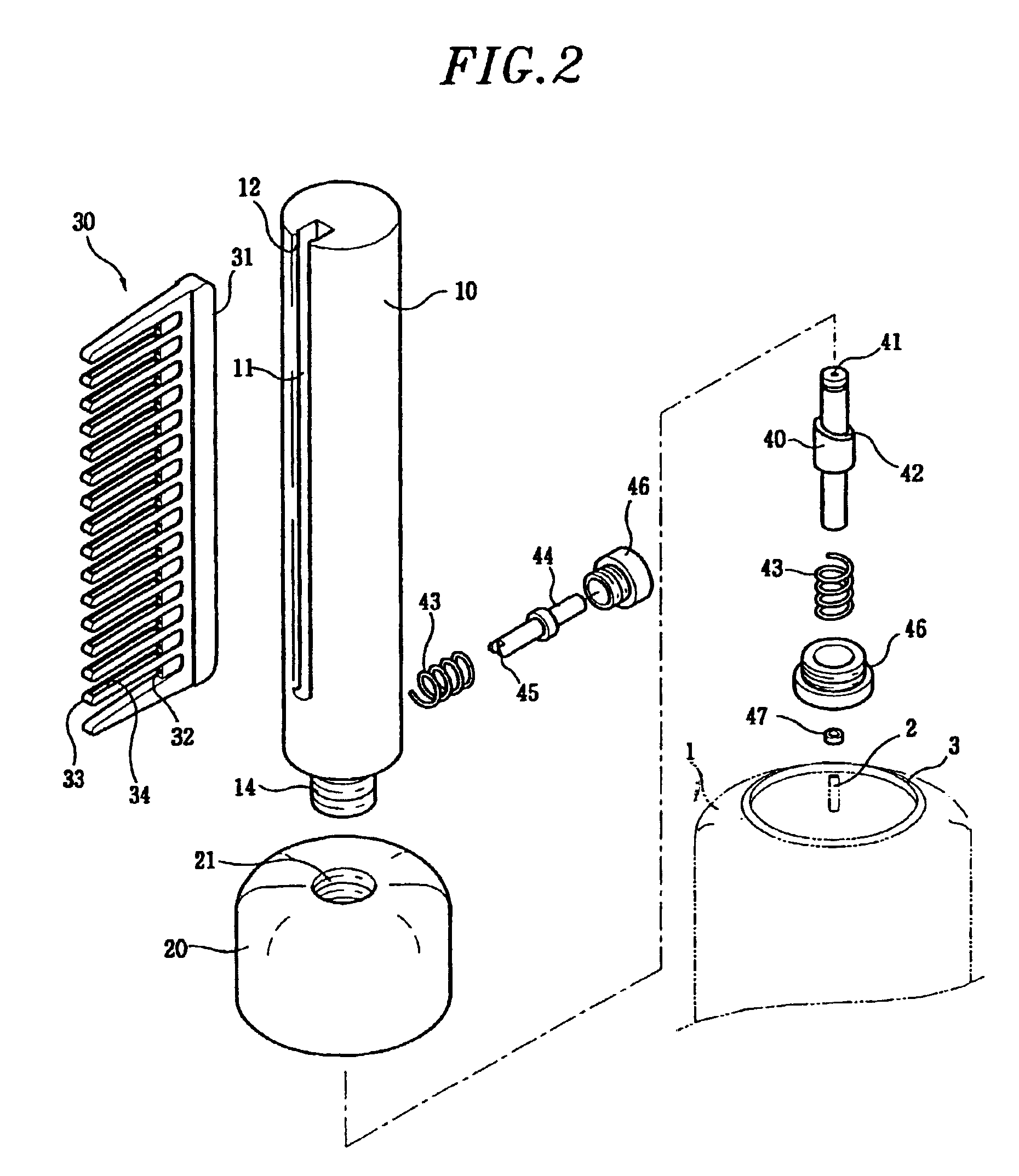
[0099]First, the body 10 and the container fixing portion 20 are assembled together. Then, the container fixing portion 20 is installed in the container 1 by engaging the stepped portion 22 of the container fixing portion 20 with the ring-shaped protrusion 3 of the container 1. After the container fixing portion 20 is installed in the container 1, the nozzle 2 is aligned with the mousse outlet 21 of the operating valve 40.

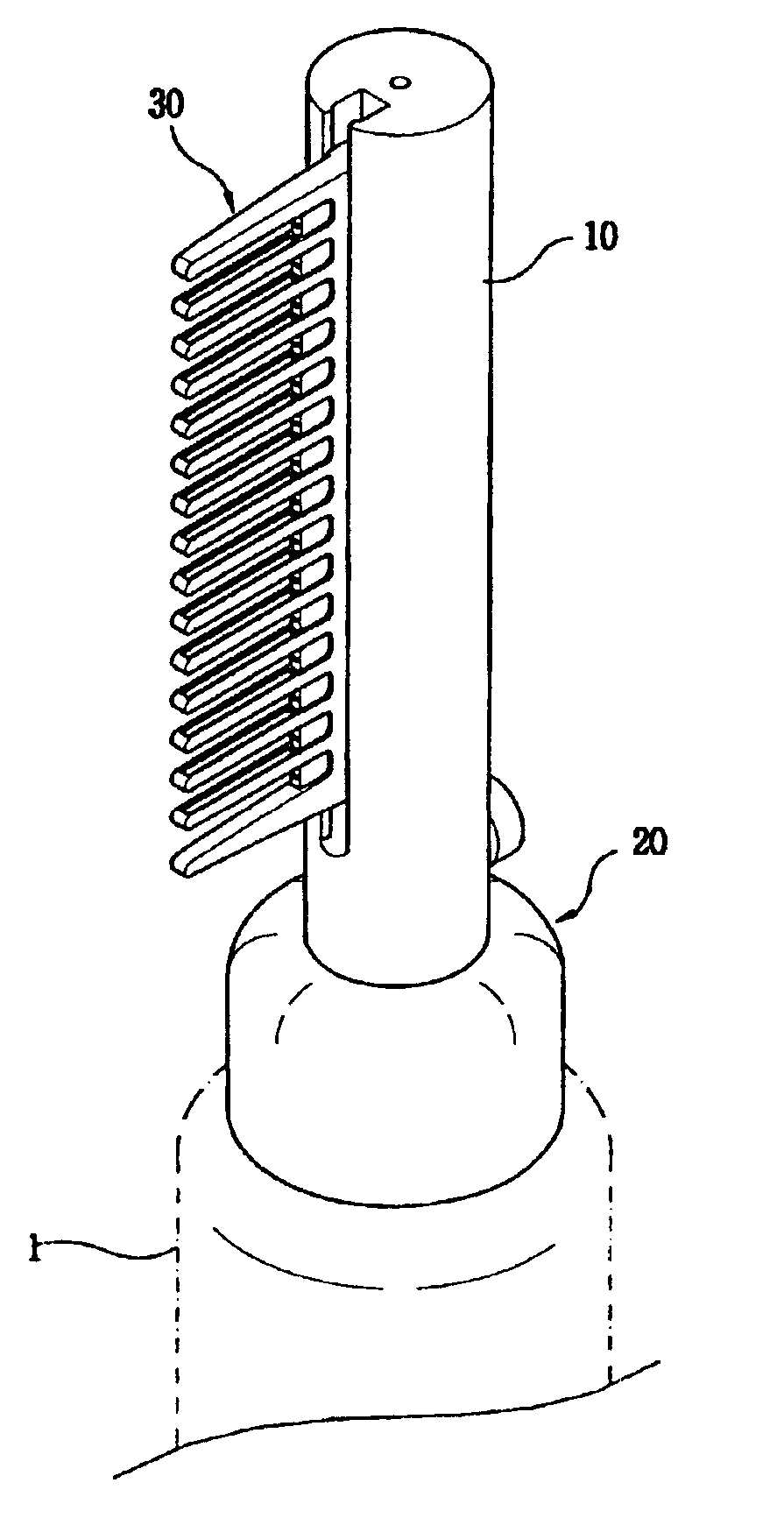
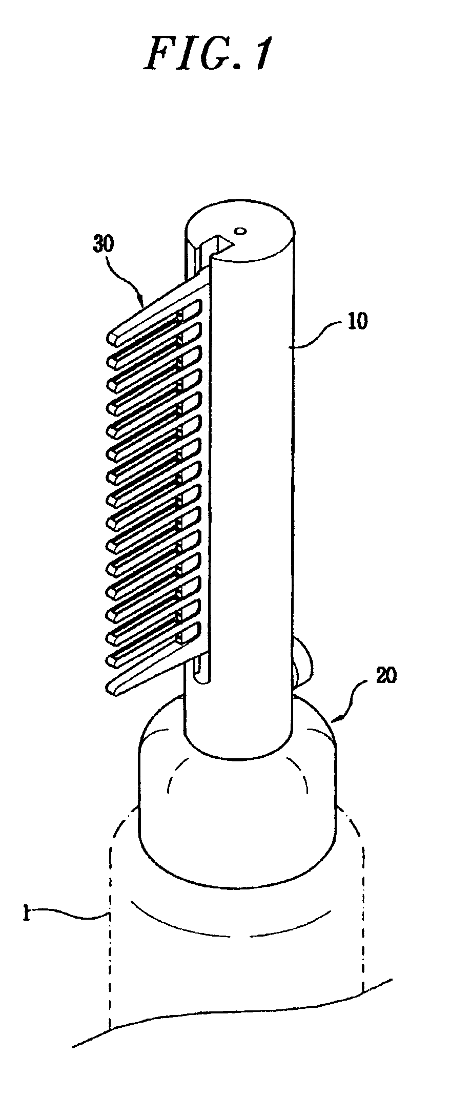
[0100]Thereafter, user selects a comb suitable for the user's purpose and then engaging the comb 30 with the body 10 by inserting it into the guide groove 11. On the other hand, the comb 30 may be inserted into the body 10 before the body 10 is assembled with the container 1. The body 10 need not be exchanged while mousse is remained in the container 1 while the comb is exchanged from time to time when needed.

[0101]FIGS. 4A and 4B represent cross-sectional views...

second embodiment

[0104]A second preferred embodiment of the present invention will be explained with reference to FIGS. 5 and 8. FIG. 5 shows a manner how a control bar engages with the comb. FIG. 7 shows a hair setting device in accordance with a modified FIGS. 6 and 8 show the manners how the lengths of teeth of the comb are adjusted, respectively.

[0105]As shown in FIGS. 5 and 7, the hair setting device comprises a comb 30 including a control bar 50, a body engaged with the comb 30 and delivering mousse from a container 1 to the comb 30, and a container fixing portion 20 for fixing the body 10 to the container 1.

[0106]As shown in FIG. 5, the control bar has a rectangular shape and engages with the comb 30. The control bar 50 may be made of organic resin and the thickness or the width thereof is determined such that one can move the control bar by one's hand.

[0107]For fixing the control bar 50 at a desired position on the comb 30 in order to adjust the length of the teeth, positioning protrusions ...

third embodiment

[0113]the present invention will now be described with reference to FIGS. 9 to 11.

[0114]As shown in FIG. 9, a comb 100 includes a base portion 110 and teeth 120. The comb 100 is connected to a main body 10 of a hair setting device by fitting the base portion 110 of the comb 100 into a guide groove 11 formed on the main body 10 (See FIG. 2).

[0115]Further, a storage part 111 is formed at the base portion 110 of the comb 100 and stores setting materials provided to the guide groove 11 through the main body 10 of the hair setting device. The storage part 111 includes spouting holes 112 formed therein for spouting out the setting materials supplied from a container 1 toward the space between the teeth 120. The storage part 111 stores therein a certain amount of setting materials when the setting materials are provided from the container 1 and then discharging the setting materials through the spouting holes 112 in order to control the discharging pressure or discharge rate of the spouted...


PUM


Abstract

A hair setting device comprises a setting material supply for storing hair setting material, a hollow pipe-shaped body including a guide groove formed along a lengthwise direction of the body and a slit formed at a bottom of the guide groove, the slit communicating with an inside space of the hollow pipe-shaped body, a base for fixing the hollow pipe-shaped body to the setting material supply, the base communicating with the inside space of the hollow pipe-shaped body and including an inner surface enclosing a nozzle of the setting material supply, an operating valve, including a setting material guide hole at a center portion of the operating valve, the operating valve being supported by a first spring inside the hollow pipe-shaped body, a bottom end portion of the operating valve being in contact with the nozzle of the setting material supply, a push button installed at a bottom portion of the hollow pipe-shape body in a radial direction thereof and supported by a second spring, wherein the push button is in contact with the operating valve in such a way that the operating valve is moved toward the nozzle of the setting material supply when the push button is pressed, and a comb including a base portion which is detachably engaged with the guide groove of the body and a plurality of outlets arranged in a regular interval for allowing the hair setting material to come out from the slit.

Description

FIELD OF THE INVENTION[0001]The present invention relates to a hair setting device for setting hair to have a desired shape; and, more particularly, to a hair setting device for setting a desired hair style just by combing one's hair without having one's hand stained with hair setting material such as mousseBACKGROUND OF THE INVENTION[0002]Conventionally, in order to make a desired hair style, one uses a hair dryer to make his or her hair half-dried and then fixes the hair by using hair setting material such as a hair spray, hair gel or mousse.[0003]The hair spray is used directly onto the one's hair to fix a hair style which is already in a desired shape. On the contrary, the hair gel or mousse is used to make a desired hair style while they are still wet and then dried to fix the style.[0004]Among these hair setting materials, the mousse is a viscous fluid generally filled in a container with air and, since the mousse dries fast and is easy to use, it is getting popular. When one ...

Claims


Application Information

Patent Timeline
Patent Type & Authority Patents(United States)
IPC IPC(8): A45D19/02A45D24/22A45D19/00A45D24/00A45D7/04A45D2/00
CPCA45D19/02A45D24/22
Inventor CHOI, YOUNG SIK
Owner CHOI YONG SIK
Why Eureka
Try Eureka