
Electrical signal transmission system

a transmission system and signal technology, applied in the direction of coupling device connection, two-part coupling device, electrical apparatus, etc., can solve the problems of unsatisfactory crosstalk, more of a problem, and close spacing of the terminals

Active Publication Date: 2005-07-12
MOLEX INC
View PDF10 Cites 37 Cited by
  • Summary
  • Abstract
  • Description
  • Claims
  • Application Information

AI Technical Summary

Benefits of technology

[0010]An object, therefore, of the invention is to provide a new and improved electrical signal transmission system of the character described.

Problems solved by technology

Crosstalk is undesirable because the integrity and definition of the signals transmitted by the conductors is degraded by the interfering coupled signals.
Crosstalk becomes more of a problem with relatively high frequency content signals.
This transmission is primarily due to the capacitive and inductive couplings between adjacent conductors resulting in crosstalk.
With modular plugs and jacks being utilized more and more in high frequency applications and with the miniaturization of the plugs and jacks resulting in a very close spacing of the terminals, crosstalk has become a greater problem.
However, the rerouting of the conductors or circuit traces on the circuit board to create the tuned capacitances contributes to an impedance mismatch of the entire transmission system, including the cable, connector, and circuit board, thereby negatively affecting return loss, voltage standing wave ratio, and combined system attenuation.
The use of tuned capacitive coupling alone to cancel both capacitive and inductive crosstalk is inherently unstable.
This will result in an improved return loss.

Method used


Image

  • Electrical signal transmission system
  • Electrical signal transmission system
  • Electrical signal transmission system

Examples


Embodiment Construction

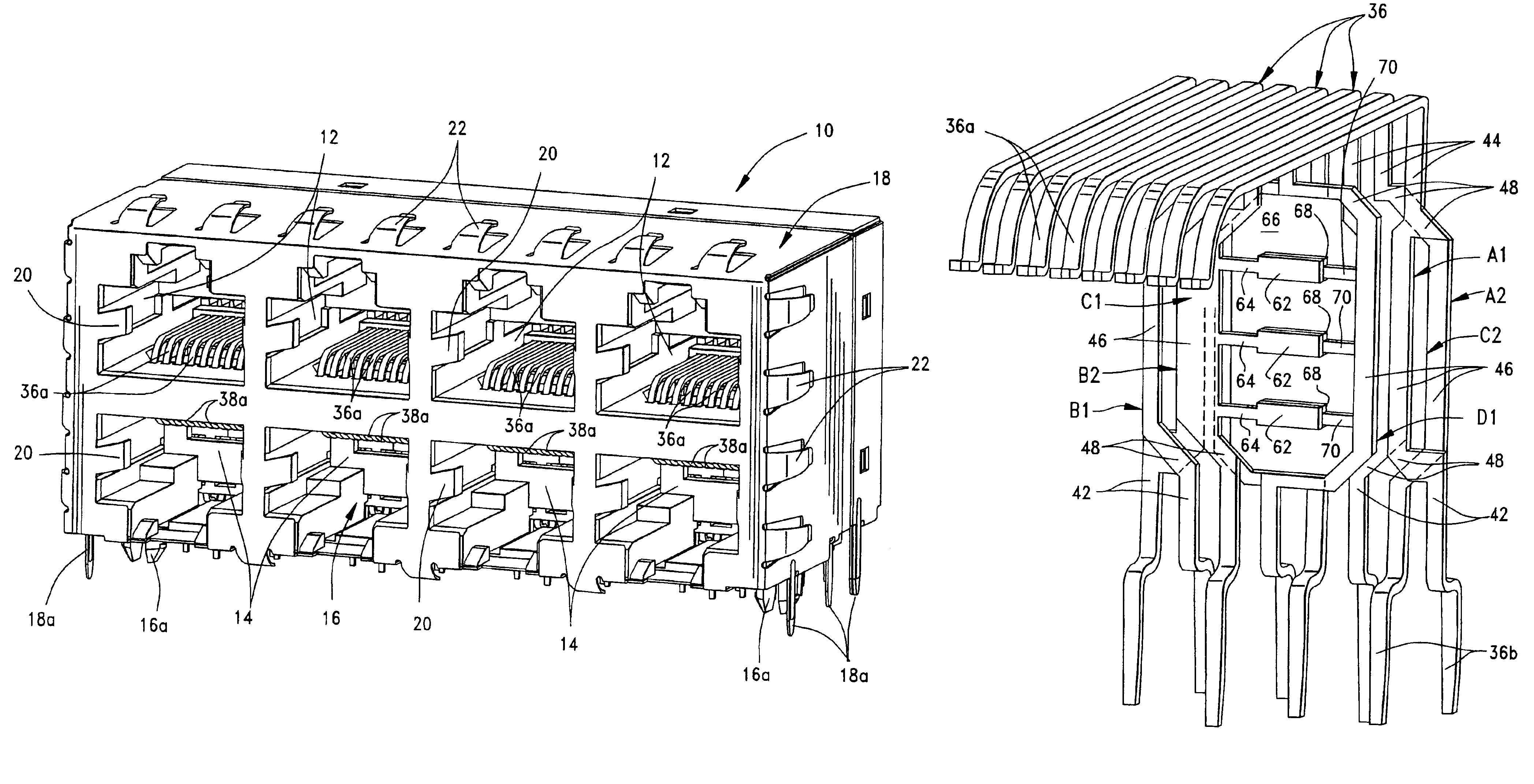
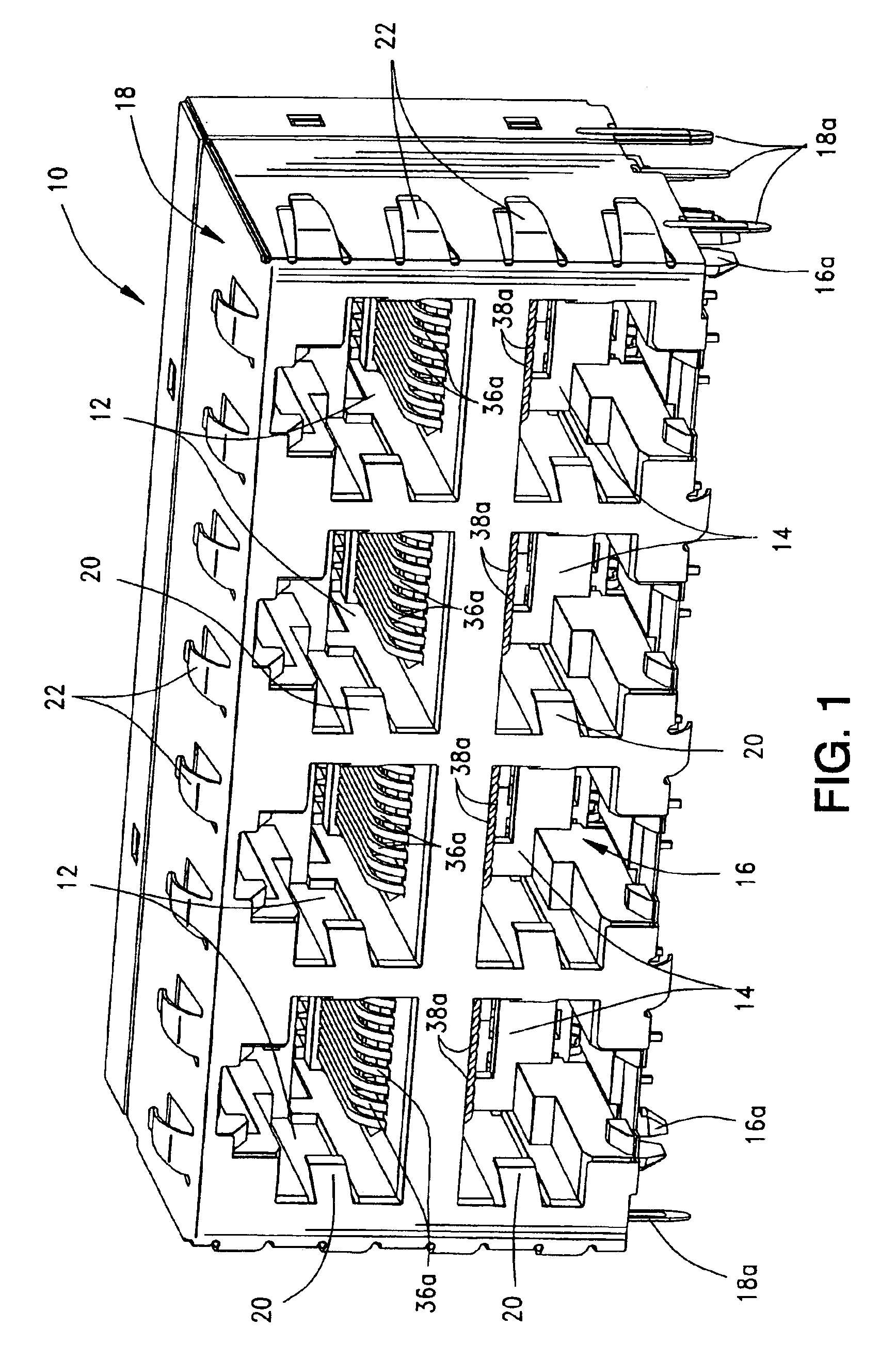
[0024]Referring to the drawings in greater detail, and first to FIG. 1, the invention is shown herein as incorporated in a multi-port jack connector, generally designated 10, which includes a plurality of top ports or receptacles 12 and a plurality of bottom ports or receptacles 14. The top ports 12 are in a horizontal row above a horizontal row of the bottom ports 14. Each of the ports 12 and 14, in essence, form a modular jack for receiving a modular plug of a configuration well known in the art.

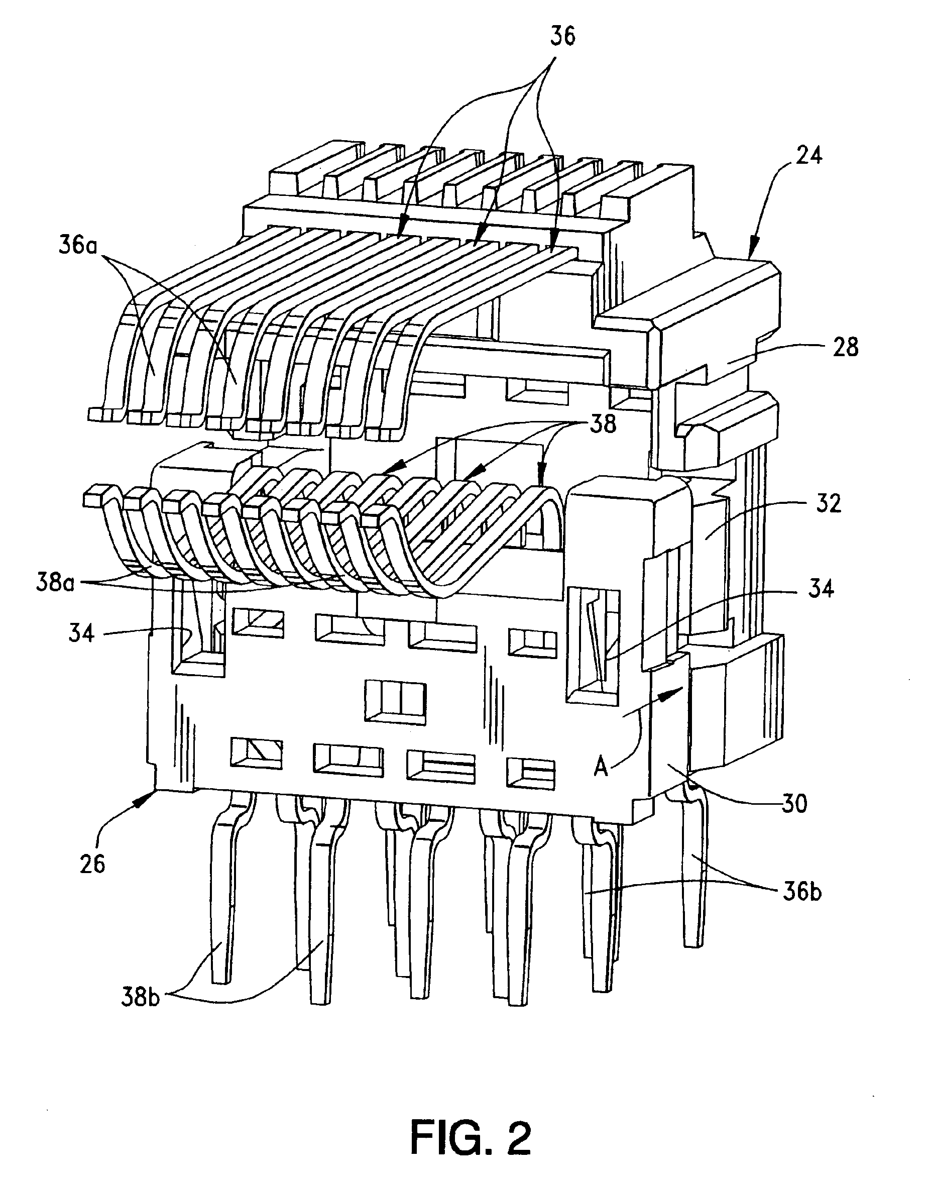
[0025]Connector 10 is of a generally conventional configuration to the extent that it includes a dielectric housing, generally designated 16, which is molded of plastic material. A conductive shell, generally designated 18, may be stamped and formed of sheet metal material and substantially surrounds the housing. The connector is designed for mounting on a printed circuit board. Therefore, housing 16 has a plurality of mounting posts 16a for insertion into appropriate mounting holes in the...


PUM


Abstract

An electrical signal transmission system includes a plurality of elongated conductors extending in a generally parallel array. The conductors have input ends at one end of the array and output ends at an opposite end of the array. Each conductor includes an elongated intermediate section and transition sections at opposite ends of the intermediate section joining the intermediate section to the input and output ends of the conductor. The array of conductors define two outside pairs of conductors and at least one inside pair of conductors. The elongated intermediate sections of the conductors in the inside pair thereof being spaced apart wider than the elongated intermediate sections of the conductors in each outside pair thereof.

Description

FIELD OF THE INVENTION[0001]This invention generally relates to the art of electrical signal transmissions and, particularly, to an improved electrical signal transmission system for a plurality of elongated, generally parallel conductors where crosstalk is reduced.BACKGROUND OF THE INVENTION[0002]Various electrical connector devices include a plurality of elongated conductors which electrically interconnect respective inputs and outputs of the connector device. As is known, when an elongated conductor is adjacent to or relatively near another elongated conductor, crosstalk typically is experienced. Crosstalk is defined as the undesirable coupling or the transmission of an electrical signal from one circuit to another nearby circuit. Crosstalk mechanisms are inductive (magnetic field) coupling and by capacitive (electric field) coupling. The level of crosstalk is increased between conductors which are generally parallel, such as the elongated conductors of a cable, modular jacks and...

Claims


Application Information

Patent Timeline
IPC IPC(8): H01R24/04H01R24/00H01R13/6464H01R13/658H01R13/6594H01R24/58
CPCH01R13/6467Y10S439/941H01R2107/00H01R13/6474H01R13/6464H01R24/64
Inventor CASHER, PATRICK R.KAMARAUSKAS, MICHAEL R.
Owner MOLEX INC
Learn More