
Connection base

a technology of connection base and base plate, which is applied in the direction of connection contact member material, support/enclosement/case, dynamo-electric machines, etc., can solve the problems of disadvantage, cumbersome base manufacturing, and prior art connection base disadvantage, and achieve the effect of eliminating prior art disadvantages

Inactive Publication Date: 2005-07-12
ABB TECH AG
View PDF5 Cites 48 Cited by
  • Summary
  • Abstract
  • Description
  • Claims
  • Application Information

AI Technical Summary

Benefits of technology

[0006]It is an object of the present invention to eliminate prior art disadvantages and provide an improved solution for a connection base for current supply cables of an electric motor. This is achieved by a connection base, the characteristic features of which are defined according to the present invention in the claims.

Problems solved by technology

Such a prior art connection base is, however, associated with a problem.
Thus, the manufacture of the base is cumbersome and the price of the connection base is disadvantageous.

Method used


Image

  • Connection base
  • Connection base
  • Connection base

Examples


Embodiment Construction

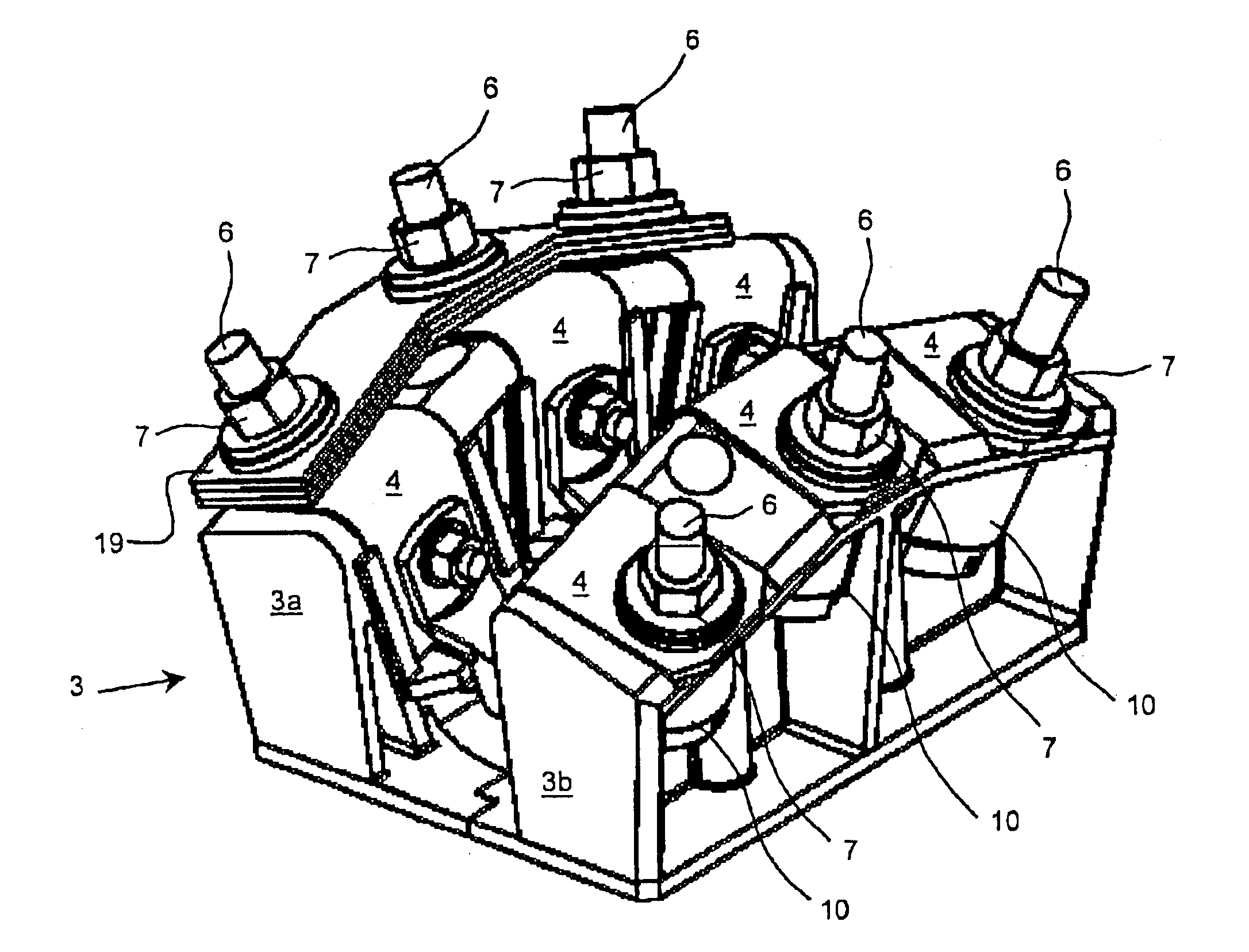
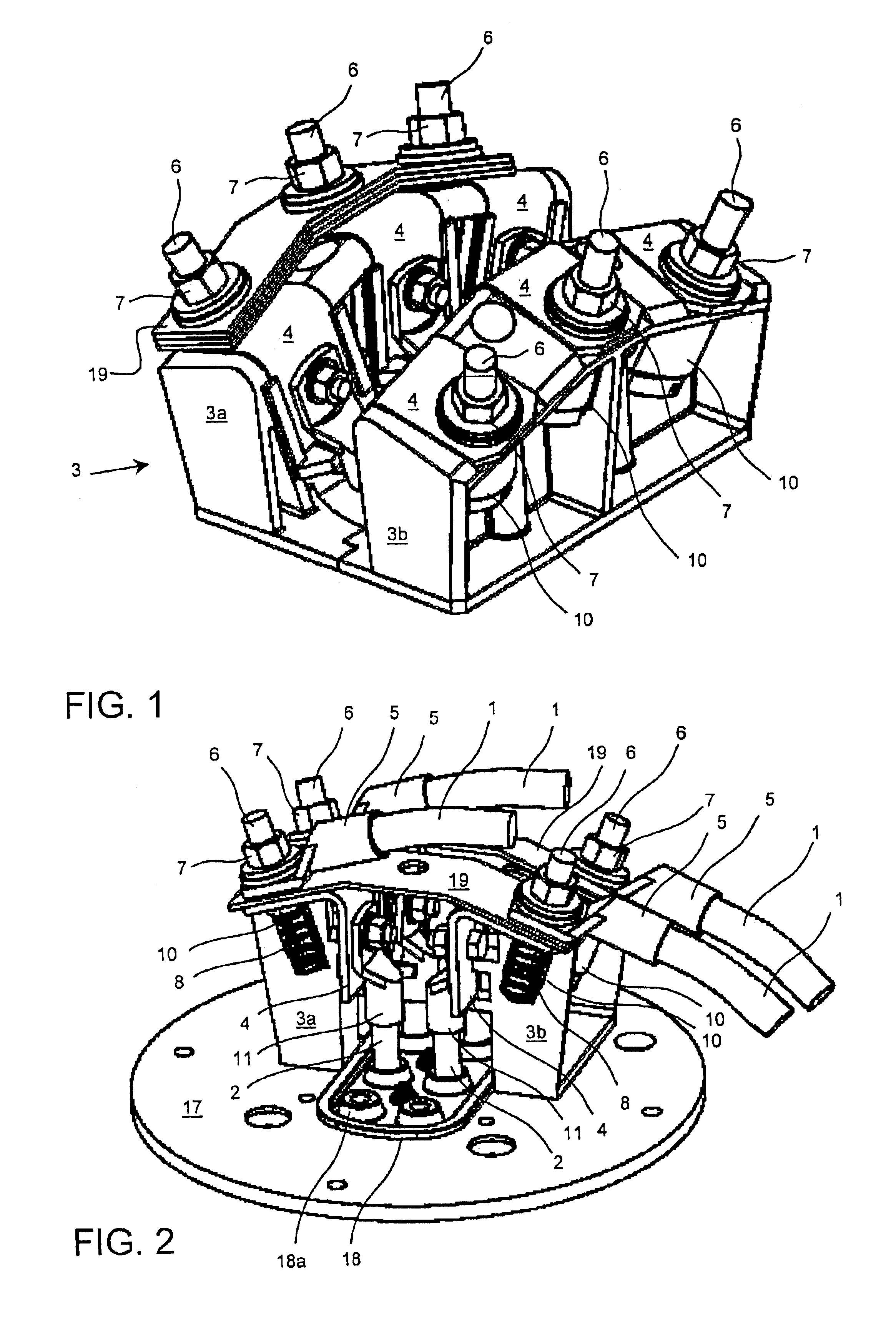
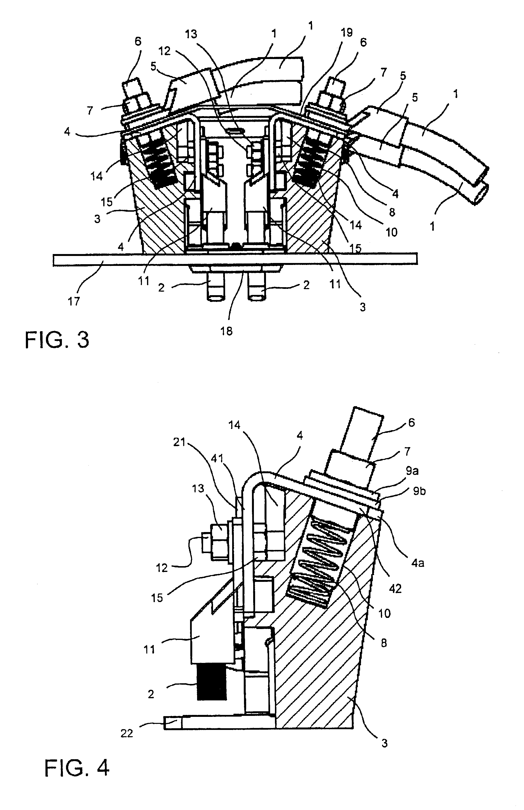
[0030]FIGS. 1 to 12 illustrate an example of the structure and operation of a connection base according to a typical preferred embodiment.

[0031]FIG. 1 is a perspective view of the structure of an embodiment of a connection base. Such a connection base is suitable for a three-phase electric motor. The connection base comprises a body 3 and terminals 4 therein. There are six terminals 4 for connecting the three-phase motor, and thus the motor can be connected either to a star connection (Y connection) or a delta connection (D connection). According to FIGS. 2 to 4, phase leads 2 coupled to the electric motor windings are connected to a first joint surface 41 of the terminals 4, and current supply cables 1 from a centre supplying the electric motor are connected to a second joint surface 42. In other words, the connection base acts as a connection point, at which the current supply cables 1 are coupled to the phase leads 2 of the electric motor windings. On the connection base, by chan...


PUM


Abstract

A connection base is presented connecting current supply cables (1) of an electric motor to phase leads (2) of electric motor windings. The connection base comprises, a body (3) made of an insulating material and terminals (4) coupled thereto, the terminals being arranged to comprise at least one angle (α) and at least a first projection (41) and a second projection (42) on the opposite sides of the angle. The body is provided with first reception means (21) for receiving at least the first projection of the terminal and for keeping it in connection with the body. Furthermore the body is provided with second reception means (14, 15) for receiving a fastening means (12, 13) to be arranged at the first projection and for locking to the body. The fastening means being arranged to lock the terminal to the body and to fasten the phase lead to the terminal.

Description

[0001]This application is a Continuation of International Application PCT / FI01 / 01045 filed on Nov. 30, 2001, which designated the U.S. and was published under PCT Article 21(2) in English.FIELD OF THE INVENTION[0002]The invention relates to a connection base for connecting current supply cables to an electric motor and, more specifically, for connecting current supply cables to phase leads coupled to electric motor windings. Connection bases of the invention are typically used in electric motors with a supply current of 100 to 1300 A.BACKGROUND OF THE INVENTION[0003]Electrical power is supplied to an electric motor from a supplying net through current supply cables. At their first end, current supply cables are connected to a centre supplying the electric motor and the second end is connected to the electric motor. A connection to the electric motor is typically carried out in a junction box of the electric motor. The ends of phase leads coupled to the windings of the electric motor...

Claims


Application Information

Patent Timeline
Patent Type & Authority Patents(United States)
IPC IPC(8): H01R4/28H01R4/30H01R4/34H02K5/22H01R4/58H01R4/48H01R4/62
CPCH01R4/304H01R4/34H02K5/225H01R4/62H01R4/4854
Inventor NYBLIN, HENRIKNYLUND, BJARNEHYYRYLAINEN, REIJOPESONEN, ERKKINEVALAINEN, HEIKKI
Owner ABB TECH AG
Learn More