Seat massager

Active Publication Date: 2005-07-12
DLHBOWLES INC
View PDF44 Cites 73 Cited by
  • Summary
  • Abstract
  • Description
  • Claims
  • Application Information

AI Technical Summary

Benefits of technology

[0028]Recognizing the need for the development of improved massagers, the present invention is generally directed to

Problems solved by technology

Natural aging, premature aging, misuse, or injury, give rise to certain spinal problems which cause a variety of symptoms, such as stiffness, pain, tingling and numbness.
. . Generally a total cycle duration that is too short (on the order, for example, of about five seconds or less) does not permit the spine to respond passively to effect a spinal mobilization, and can be distracting to the user, while a total cycle duration that is too long (on the order, for example, o

Method used


Image

  • Seat massager
  • Seat massager
  • Seat massager

Examples


Embodiment Construction

[0054]Before explaining at least one embodiment of the present invention in detail, it is to be understood that the invention is not limited in its application to the details of construction and to the arrangements of the components set forth in the following description or illustrated in the drawings. The invention is capable of other embodiments and of being practiced and carried out in various ways.

[0055]Also, it is to be understood that the phraseology and terminology employed herein are for the purpose of description and should not be regarded as limiting. For example, the discussion herein may sometimes refer to “inflatable air bladders;” however, it should be apparent that the inventive concepts described herein are applicable to inflatable bladders containing any type of fluid.

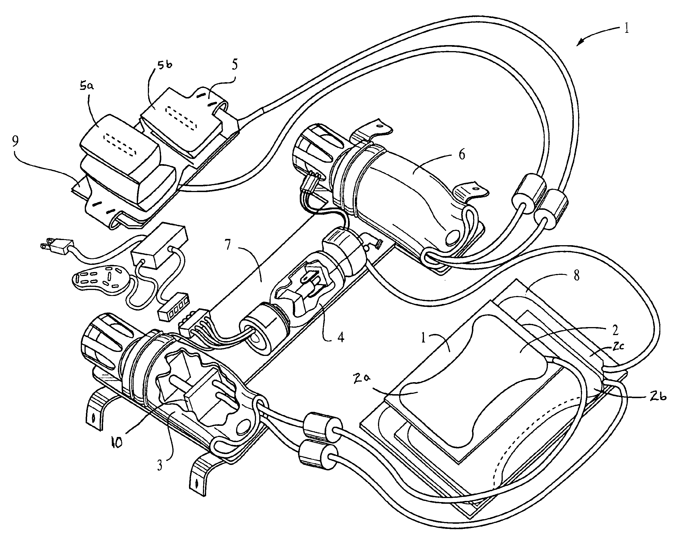
[0056]The present invention generally relates to methods and apparatus for causing a portion of a chair or seat, or other body supporting device, to massage a surface area of one who is using them. FIG...


PUM


Abstract

A seat massager for massaging a person's back has, according to the present invention, a pair of inflatable, massage bladders configured so as to be received in close proximity to a person's back and oriented so that these bladders share an overlaid portion with each other, a pump that supplies fluid to the bladders, a fluidic having an inlet and two exhaust ports, a conduit that connects each of the fluidic exhaust ports to one of the pair of bladders, wherein the fluidic is configured so as to yield alternating flow from the exhaust ports that cyclically inflates and deflates each of the bladders so as to provide a massaging sensation to the back. This massager may also include an inflatable support bladder positioned beneath the massage bladders, another pump that supplies fluid to this support bladder, and a carrier plate on which the pumps are mounted, this plate being configured so as to aid in attaching the seat massager to the frame of a seat into which the seat massager is to be installed.

Description

CROSS-REFERENCE TO RELATED APPLICATION[0001]This application is related to the following U.S. patent applications:[0002]Ser. No. 09 / 567,890, filed May 10, 2000, which claims the benefits of Provisional Patent Applications Nos. 60 / 133,676 filed May 11, 1999, 60 / 140,744 filed Jun. 25, 1999 and Ser. No. 60 / 163,154 filed Nov. 2, 1999;[0003]Ser. No. 09 / 634,591, filed Aug. 8, 2000 but now abandoned, which claimed the benefits of Provisional Patent Application No. 60 / 147,504 filed Aug. 9, 1999;[0004]Ser. No. 09 / 713,328, filed Nov. 16, 2000 which claims the benefit of Provisional Patent Application No. 60 / 167,695 filed Nov. 29, 1999;[0005]Ser. No. 09 / 773,631, filed Feb. 2, 2001 but now abandoned, which claimed the benefit of Provisional Patent Application No. 60 / 180,123 filed Feb. 3, 2000, and[0006]Ser. No. 09 / 982,085, filed Oct. 19, 2001, which claims the benefit of Provisional Patent Application No. 60 / 241,791 filed Oct. 20, 2000.BACKGROUND OF THE INVENTION[0007]1. Field of the Invention[...

Claims


Application Information

Patent Timeline
IPC IPC(8): A61H1/00A61H23/04
CPCA61H23/04A61H2201/0134A61H2201/0138A61H2201/0149A61H2205/081A61H2205/10A61H2201/0142A61H2201/0146A61H2201/1623A61H2201/164
Inventor HESTER, RUSSELL D.ROMACK, ALAN S.BERNING, KEITH R.MARSDEN, THOMAS G.KOROBKOV, ROSA
Owner DLHBOWLES INC
Why Eureka
Try Eureka