

Top-loading monopole antenna apparatus with short-circuit conductor connected between top-loading electrode and grounding conductor
a top-loading monopole antenna and short-circuit conductor technology, which is applied in the direction of antennas, antenna details, antenna adaptation in movable bodies, etc., can solve the problems of failure to achieve impedance matching at a lower frequency, and large size of circular flat-plate electrodes. achieve the effect of easy impedance matching
- Summary
- Abstract
- Description
- Claims
- Application Information
AI Technical Summary
Benefits of technology
Problems solved by technology
Method used
Image

Examples
first preferred embodiment
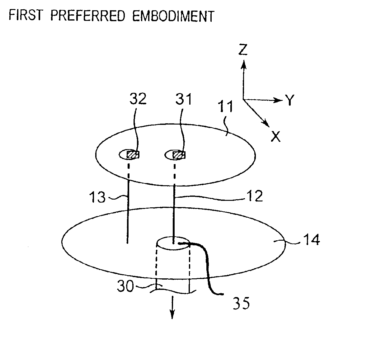
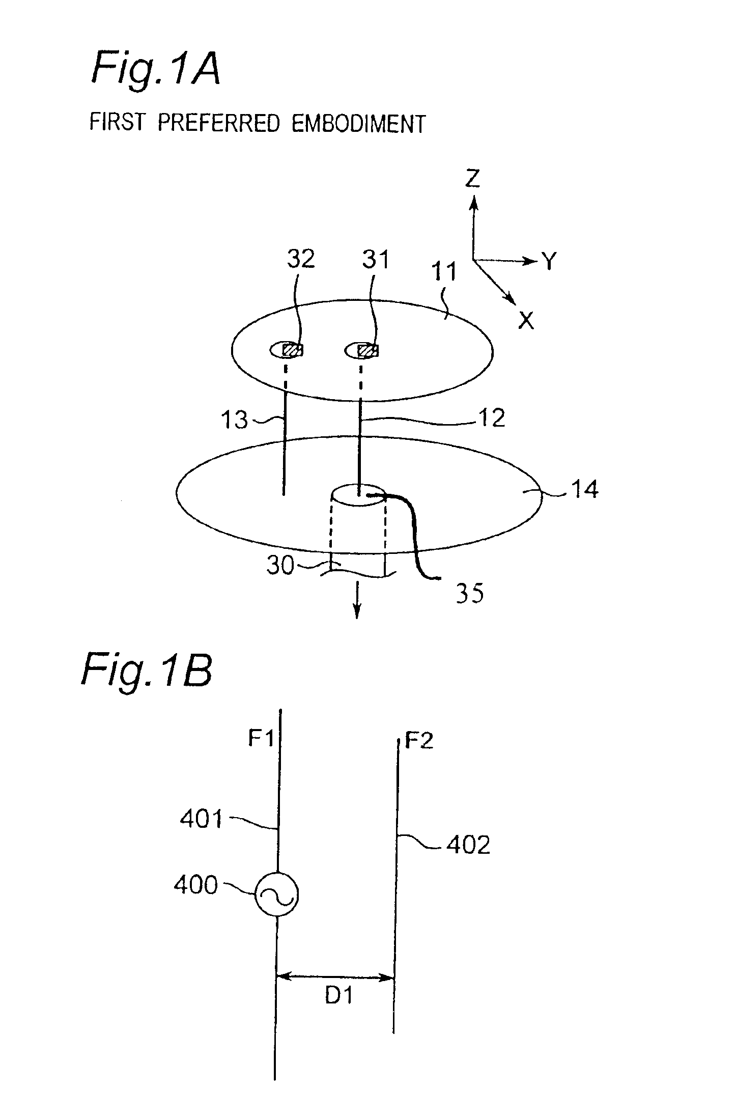
[0125]FIG. 1A is a perspective view showing a structure of a top-loading monopole antenna apparatus according to the first preferred embodiment of the present invention, and FIG. 1B is a schematic view showing a prototype or original antenna apparatus which is equivalent to the top-loading monopole antenna apparatus of FIG. 1A. The top-loading monopole antenna apparatus of the first preferred embodiment provides means for solving the first problem of the prior art concerning the above-mentioned impedance matching, and the structure of the present antenna apparatus will be described hereinbelow with reference to FIGS. 1A and 1B.
[0126]The top-loading monopole antenna apparatus of the first preferred embodiment shown in FIG. 1A is characterized as being different from the top-loading monopole antenna apparatus of the prior art shown in FIG. 39 at least with respect to the following points.
[0127](1) One end of the linear conductor element 12 on the side of a top-loading electrode 11 (he...
second preferred embodiment
[0151]FIG. 4 is a perspective view showing a structure of a top-loading monopole antenna apparatus according to the second preferred embodiment of the present invention. The top-loading monopole antenna apparatus of the second preferred embodiment provides means for solving the above-mentioned third problem of the prior art concerning the band. As shown in FIG. 4, the second preferred embodiment is characterized in that a parasitic element 61 is provided at a predetermined distance from the electrode 11 without being in contact with the electrode 11 so as to extend along an outer edge portion of the circular flat-plate-shaped electrode 11 so that predetermined electromagnetic field coupling is caused, as compared with the prior art of FIG. 39. In this case, one end of the parasitic element 61 is electrically connected with the grounding conductor 14, and the parasitic element 61 then extends so as to be parallel to the linear conductor element 12. After the parasitic element 61 is b...
third preferred embodiment
[0155]FIG. 6 is a perspective view showing a structure of a top-loading monopole antenna apparatus according to the third preferred embodiment of the present invention. The top-loading monopole antenna apparatus of the third preferred embodiment is characterized in being different from the top-loading monopole antenna apparatus of the prior art shown in FIG. 39 at least with respect to the following points. That is, a ring-shaped space 81 is formed at one end of the short-circuit conductor 13 on the side of the electrode 11 and its neighborhood portion, and the one end of the short-circuit conductor 13 is electrically connected with the electrode 11 through a reactive element 82. The other structure is similar to that of the prior art.
[0156]In the antenna apparatus constituted as described above, the resonance frequency is changed by changing the reactance value of the reactive element 82 provided between the circular flat-plate-shaped electrode 11 and the short-circuit conductor 13...
PUM
 Abstract
Description
Claims
Application Information