Mounting apparatus of electronic parts and mounting methods of the same

a technology for mounting apparatuses and electronic parts, applied in metal working apparatuses, printed circuit manufacture, manufacturing tools, etc., can solve problems such as interference and/or waiting time, and achieve the effect of improving mounting efficiency

Inactive Publication Date: 2005-07-19
PANASONIC CORP
View PDF7 Cites 27 Cited by
  • Summary
  • Abstract
  • Description
  • Claims
  • Application Information

AI Technical Summary

Benefits of technology

[0008]Accordingly, it is an object of the present invention to provide an electronic parts mounting apparatus and method capable of improving mounting efficiency when the electronic parts mounting apparatus handles different kinds of substrates with various widths.

Problems solved by technology

This difference causes mounting operations and sequences between these beams to be unbalanced, which may cause undesirable interferences and / or waiting time between these beams.

Method used


Image

  • Mounting apparatus of electronic parts and mounting methods of the same
  • Mounting apparatus of electronic parts and mounting methods of the same
  • Mounting apparatus of electronic parts and mounting methods of the same

Examples


first embodiment

(First Embodiment)

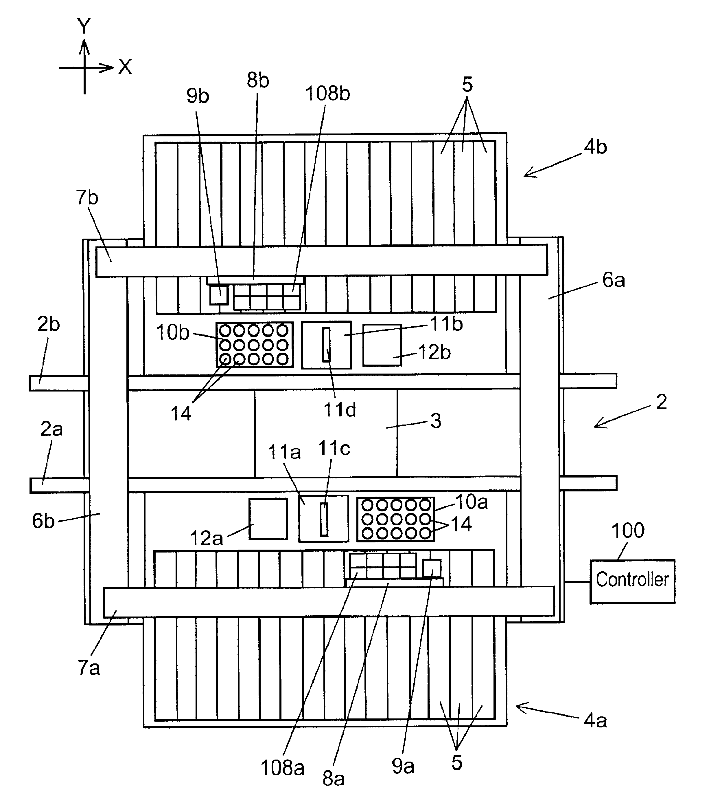
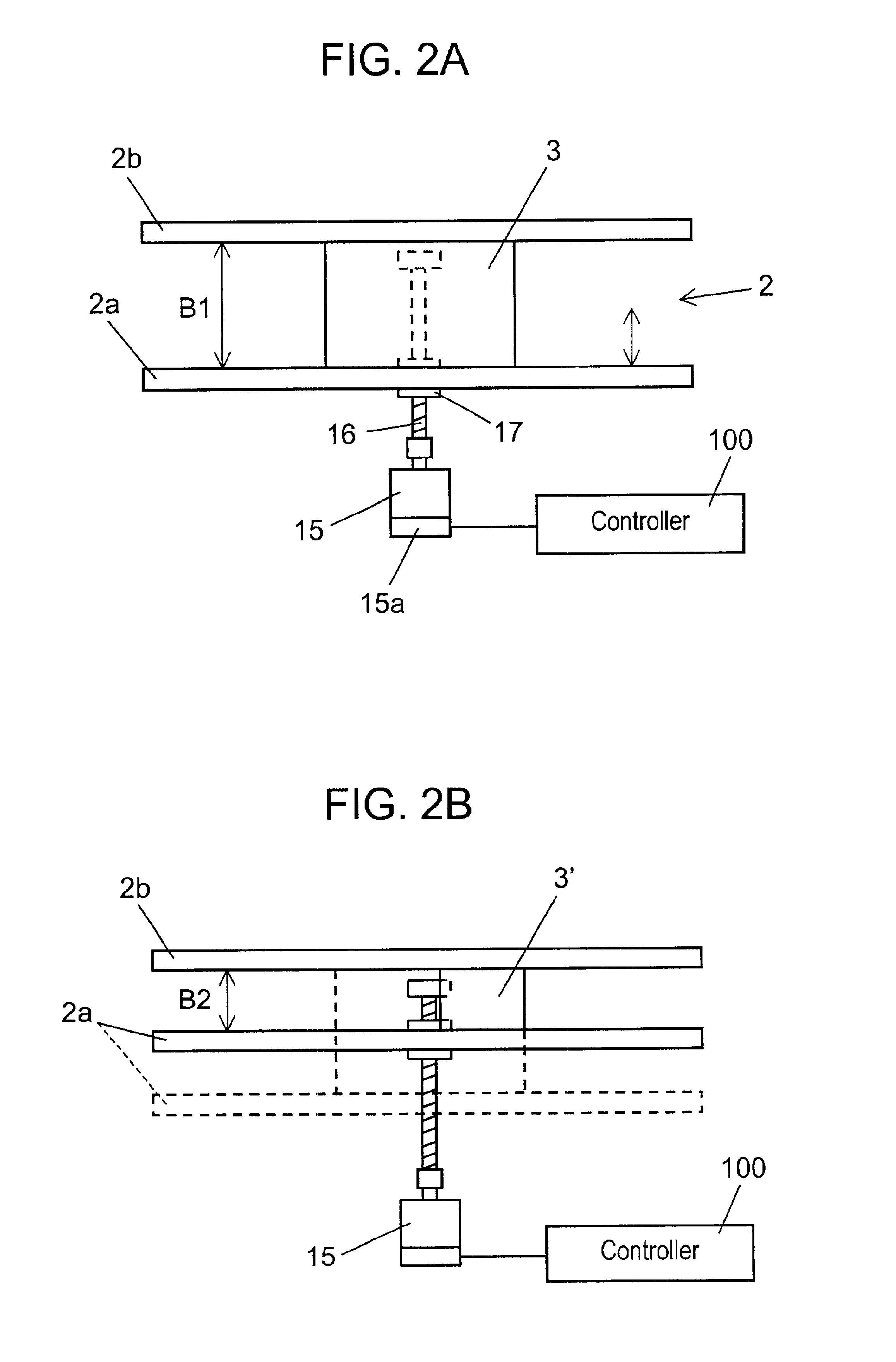
[0019]Referring to FIG. 1, an electronic parts mounting apparatus according to the first embodiment of the present invention is shown. A transfer passage 2 is formed in a direction of an X-axis at the center of a bed 1. The transfer passage 2 is formed by transfer rails 2a and 2b such that a substrate 3 is carried between the transfer rails 2a and 2b and is set in position. The transfer rail 2a is movable in a direction of a Y-axis which is perpendicular to the carrying direction, that is the direction of the X-axis. A transfer width, that is assistance between the transfer rails 2a and 2b, is changeable according to a size of the substrate 3 by moving the transfer rail 2a in the direction of the Y-axis.

[0020]Parts supply members 4a and 4b for supplying electronic parts are provided on both sides of the transfer passage 2. A number of tape feeders 5 are provided in a row at each of the parts supply members 4a and 4b. Each of the tape feeders 5 houses electronic par...

second embodiment

(Second Embodiment)

[0048]Referring to FIGS. 5, 6 and 7, a second embodiment of the present invention will now be described. This second embodiment is an arrangement of the first embodiment such that the transfer rails 2a and 2b move integrally with other elements including the parts supply members 4a and 4b. In the second embodiment, components which are substantially the same as those in the first embodiment are assigned the same reference numerals.

[0049]Referring to FIGS. 5 and 6, a pair of guide rails 31 are mounted on a base 11a of the bed 1 along the Y-axis on each side of the transfer passage 2. Sliders 32 are loosely fitted with the guide rails 31 so that the sliders 32 slide on the guide rails 31. The sliders 32 are also attached to the lower surfaces of movable bases 30a and 30b horizontally located at each side of the transfer passage 2.

[0050]The parts supply members 4a and 4b including the tape feeders 5 are placed on the movable bases 30a and 30b, respectively. The trans...


PUM

PropertyMeasurementUnit
sizeaaaaaaaaaa
widthaaaaaaaaaa
sizesaaaaaaaaaa

Abstract

An apparatus and method for mounting electronic parts wherein a transfer width between a pair of transfer rails is changeable according to a size of a substrate. A mounting head picks up electronic parts at a parts supply member and keeps its stand-by position for mounting the electronic parts on the substrate. The stand-by position of the mounting head is determined according to the changed amount of the transfer width.

Description

CROSS REFERENCE TO RELATED APPLICATION[0001]This application is based upon and claims the benefit of priority of Japanese Patent Application No. 2001-98681 filed on Mar. 30, 2001, the contents of which are incorporated herein by reference.BACKGROUND OF THE INVENTION[0002]1. Field of the Invention[0003]The present invention relates to an apparatus and method for mounting electronic parts onto a substrate.[0004]2. Description of Related Art[0005]U.S. Pat. No. 5,778,525 discloses a conventional component mounting apparatus having two mounting heads for picking up electronic parts from component supply tables and mounting them onto a substrate (circuit board).[0006]This type of the mounting apparatus, a so-called two-beam type, generally handles several kinds of substrates with various sizes. Every time the size of the substrate is changed, some adjustments, for example, changing a transfer width between transfer rails, are carried out. In this case, the transfer width is generally chan...

Claims


Application Information

Patent Timeline
Patent Type & Authority Patents(United States)
IPC IPC(8): H05K13/00H05K13/04
CPCH05K13/0069H05K13/0452Y10T29/49144Y10T29/4913Y10T29/53174Y10T29/53178Y10T29/49133Y10T29/49131H05K13/0061H05K13/0411
Inventor NAGAO, KAZUHIDETSUTSUMI, TAKUYANODA, TAKAHIROSUMI, HIDEKI
Owner PANASONIC CORP
Why Eureka
Try Eureka