
Control device for a lock mechanism

a control device and lock mechanism technology, applied in mechanical control devices, keyhole guards, restricting/preventing/returning movement of parts, etc., can solve problems such as difficulty in door construction and sometimes giving of lock mechanism operation with a key, and achieve the effect of small motor and large for

Inactive Publication Date: 2005-07-19
VAN PARYS REMI EMIEL
View PDF14 Cites 29 Cited by
  • Summary
  • Abstract
  • Description
  • Claims
  • Application Information

AI Technical Summary

Benefits of technology

[0011]Actually, the control device only takes over the function of the key of the lock mechanism. The gear wheel transmissions make it possible for the mesh element to exert a relatively large force on the lock mechanism with a relatively small motor.

Problems solved by technology

The operation of lock mechanisms with a key may sometimes give rise to problems, for example because the keyhole cannot be found in the dark, or because people do not have a steady hand and find it difficult to put the key in the keyhole.
Due to the built-in motor, these special lock mechanisms are relatively large and as a result difficult to be built in in a door.

Method used


Image

  • Control device for a lock mechanism
  • Control device for a lock mechanism
  • Control device for a lock mechanism

Examples


Embodiment Construction

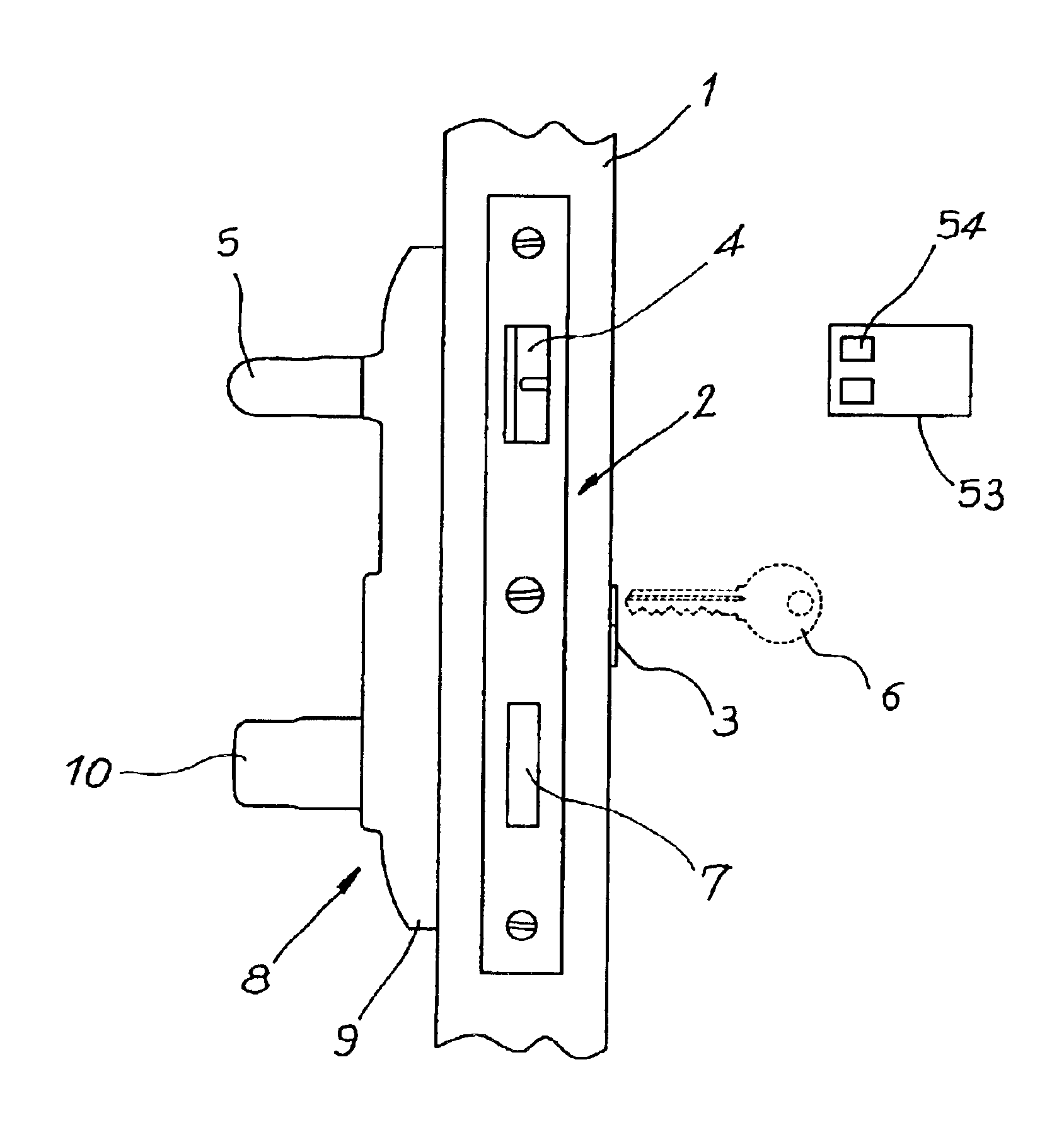
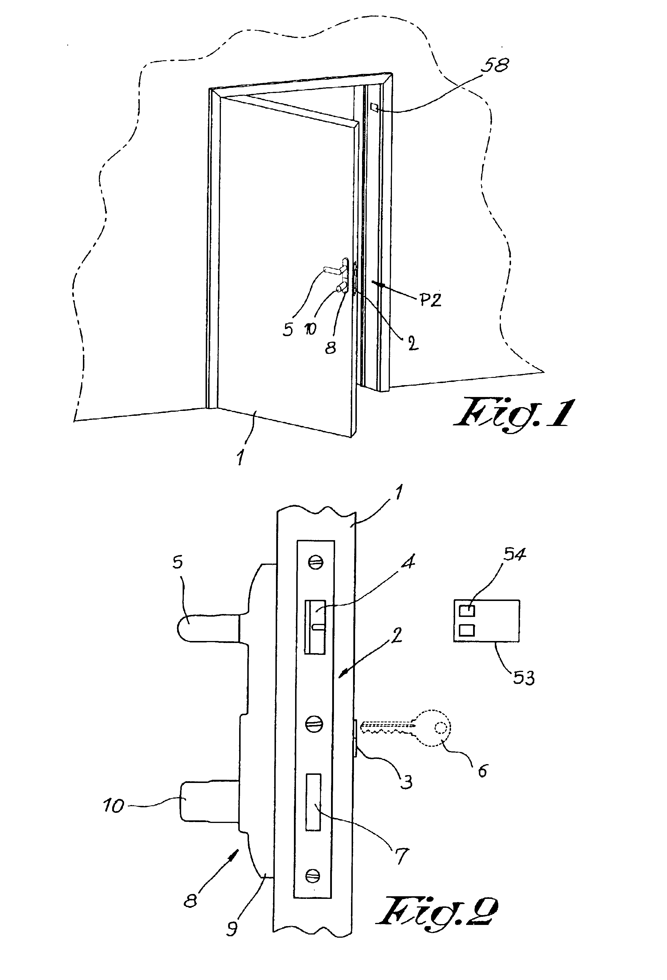
[0028]FIGS. 1 and 2 represent an entrance door 1 provided with a conventional lock mechanism 2 with a cylinder 3. The single lock 4 can be operated in the usual manner by means of a handle 5 provided on the inside of the door 1, whereas this single lock 4 as well as the night latch 7 can be operated from the outside with a key 6.

[0029]The single lock 4 and the night latch 7 can be operated by means of a control device 8 according to the invention from the inside as well as from the outside.

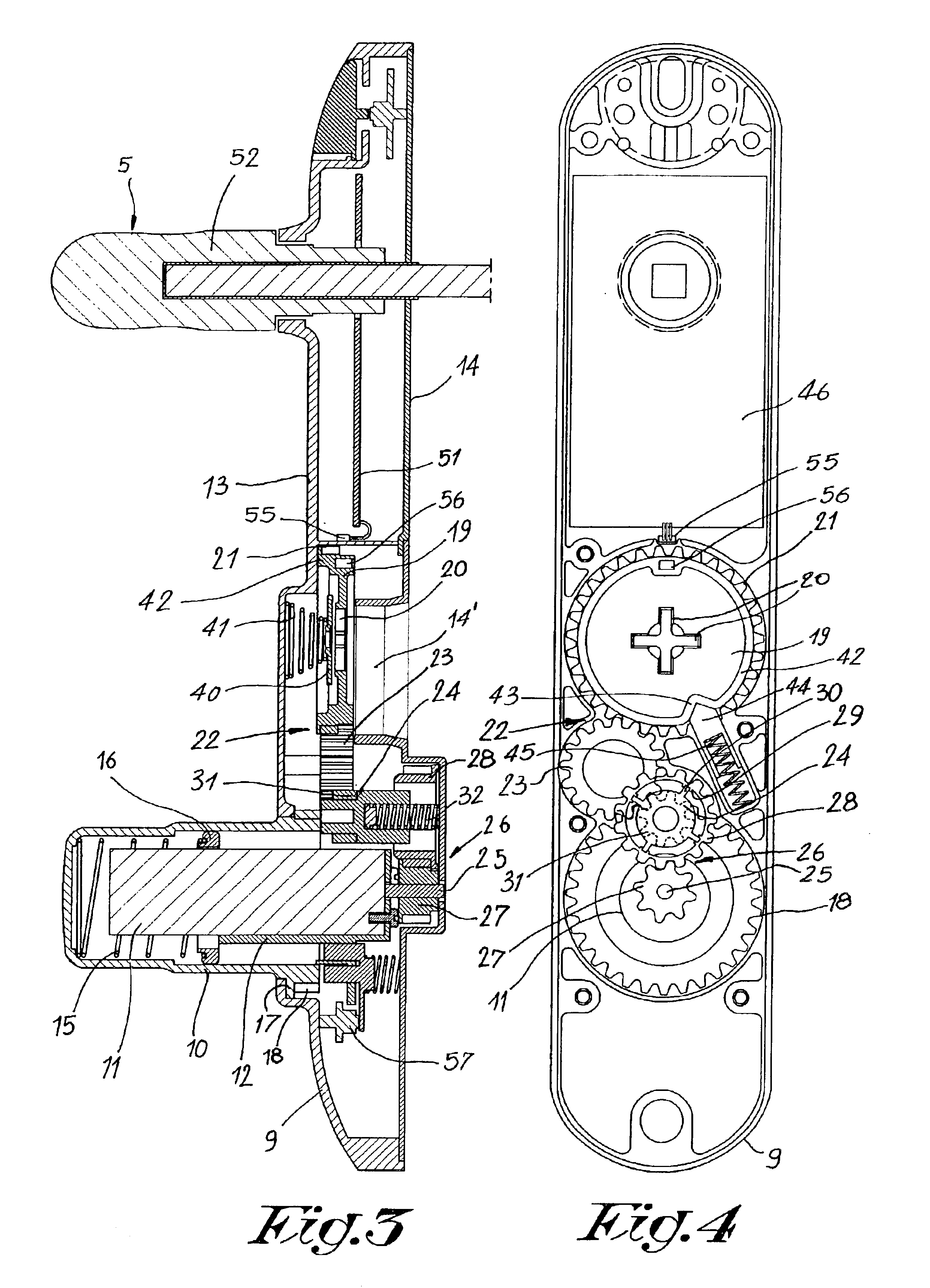
[0030]As is represented in detail in FIGS. 3 to 7, this control device 8 comprises a housing 9 provided on the inside of the door 1; a hollow hand knob 10 provided on the housing such that it can rotate at an angle and can be axially moved over a distance; an electric motor 11 erected in this hollow hand knob 10 fixed to the housing 9 by means of a holder 12.

[0031]In order to make it possible to mount parts inside the housing 9, it consists of a front wall 13 through which the handle 5 and the han...


PUM


Abstract

The present invention concerns a control device for a lock mechanism, in particular a lock mechanism comprising a housing; a hollow hand knob to be pressed on which is mounted on the housing such that it can rotate and which has a far end with teeth inside this housing; an electric motor situated in the hollow hand knob, applied on the housing in a fixed manner and situated with its drive shaft in this housing; a mesh element mounted in the housing in a rotatable manner and provided with teeth for meshing with a key part of the lock mechanism and a gear wheel which can be axially moved by the hand knob.

Description

[0001]This application claims the benefit of Belgian Application No. 2001 / 0604 filed Nov. 19, 2001.BACKGROUND OF THE INVENTION[0002]1. Field of the Invention[0003]The present invention concerns a control device for a lock mechanism, in particular a lock mechanism with a cylinder, which control device can operate the lock mechanism with a key as well as with a motor.[0004]2. Discussion of the Related Art[0005]The operation of lock mechanisms with a key may sometimes give rise to problems, for example because the keyhole cannot be found in the dark, or because people do not have a steady hand and find it difficult to put the key in the keyhole.[0006]That is why remote-controlled key mechanisms have been developed, for example with a built-in transmitter in the head of the key.[0007]Special lock mechanisms are used to this end with an internal electric motor for moving the dead bolt.[0008]Due to the built-in motor, these special lock mechanisms are relatively large and as a result diff...

Claims


Application Information

Patent Timeline
Patent Type & Authority Patents(United States)
IPC IPC(8): E05B47/00
CPCE05B47/0012E05B2047/002E05B2047/0031E05B2047/0091Y10T70/5978Y10T70/5832Y10T70/7051Y10T70/7113
Inventor VAN PARYS, REMI EMIEL
Owner VAN PARYS REMI EMIEL
Learn More