Planter bracket assembly for supporting appurtenances in substantial alignment with the seed tube
a planter bracket and appurtenance technology, which is applied in the direction of potato planters, furrow making/covering, agricultural tools and machines, etc., can solve the problems of affecting the flow of liquid applicator tubes, and affecting the stability of the liquid applicator tubes
- Summary
- Abstract
- Description
- Claims
- Application Information
AI Technical Summary
Benefits of technology
Problems solved by technology
Method used
Image
Examples
first embodiment
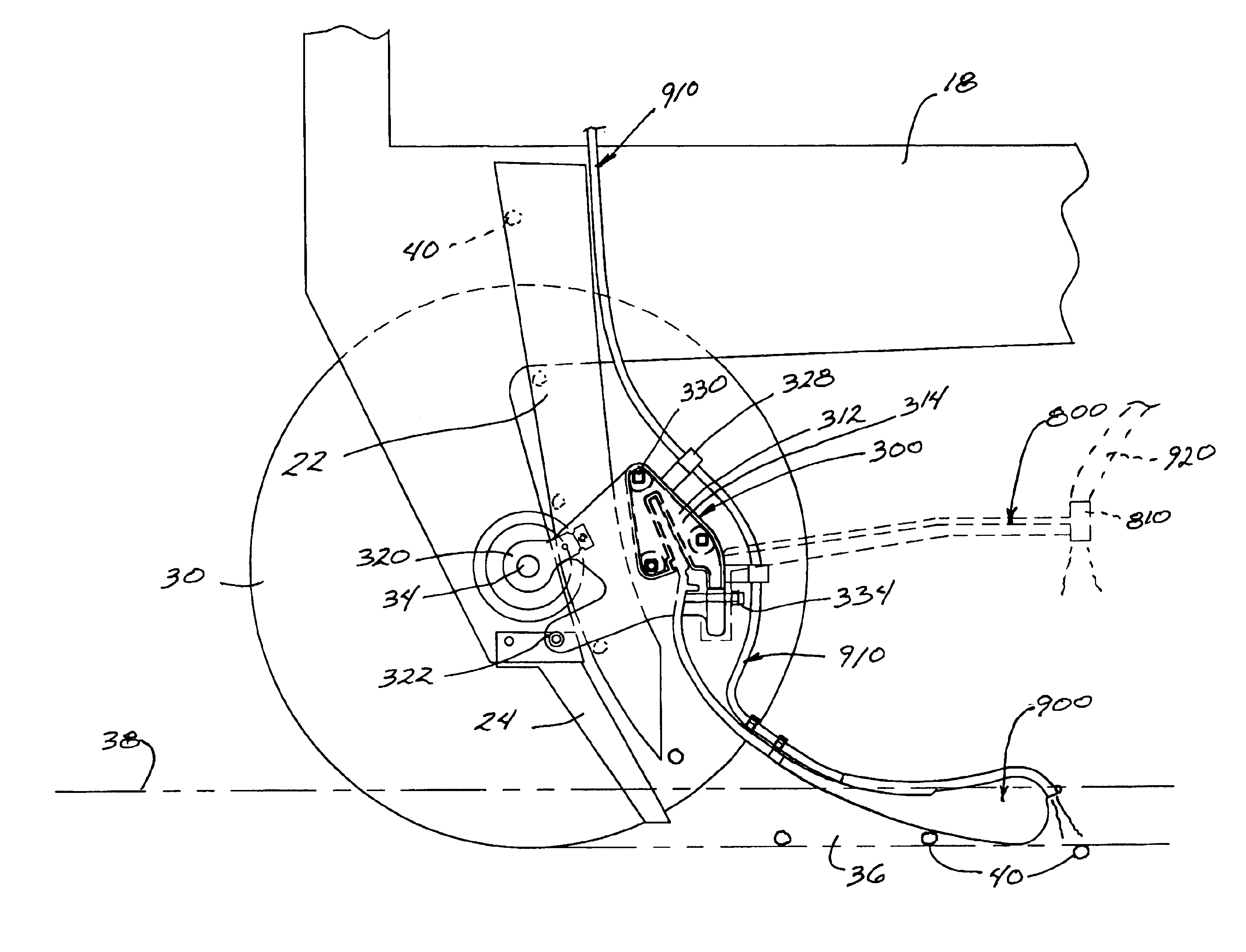
[0034]FIGS. 6-14 illustrate various embodiments of improved bracket assemblies comprising the present invention. Referring, first to FIG. 6, an improved bracket assembly 300 is shown. As with the existing bracket assembly 100, this first improved bracket assembly 300 comprises a housing 312 having opposing, preferably substantially mirror-image, first and second sides 314, 316. The housing 312 preferably includes mounting structure 318 comprising upper and lower ears 320, 322. However, rather than the ears 320, 322 formed from thermoplastic material as in the existing bracket assembly 100, the upper ears 320 comprise metal ear tabs preferably integrally attached with the housing 312 by inserting molding the metal ear tabs 320 during the injection molding process when forming the housing 312. Alternatively, rather than insert molding, the metal ear tabs 320 may be integrally attached to the housing 312 by a rivet connection, bolted connection, adhesives or welding by any know means, ...
embodiment 500
[0041]As previously identified, the third improved bracket assembly embodiment 500 includes a passageway 528 defined by the walls 524. The passageway 528 extends through at least a portion of the housing 512 through which a liquid conduit 910 is receivable. Accordingly, if in-furrow liquid application is desired, one end of the liquid conduit 910 is inserted through the passageway 528 within the housing 512. Depending on the type of resilient tool 900 installed in the cavity 526, the liquid conduit 910 may extend along the back of the resilient tool 900, terminating at the rearward end of the resilient tool 900 as shown in FIG. 11. The other end of the liquid conduit 910 is fluidly connected to a liquid supply reservoir (not shown) located on the planter or prime mover. In operation, liquid is pumped from the liquid supply reservoir through the liquid conduit 910 for depositing in the furrow, preferably behind the resilient tool 900.
[0042]It should be understood that although the pr...
PUM
 Abstract
Description
Claims
Application Information
 - R&D
- Intellectual Property
- Life Sciences
- Materials
- Tech Scout
- Unparalleled Data Quality
- Higher Quality Content
- 60% Fewer Hallucinations
Browse by: Latest US Patents, China's latest patents, Technical Efficacy Thesaurus, Application Domain, Technology Topic, Popular Technical Reports.
© 2025 PatSnap. All rights reserved.Legal|Privacy policy|Modern Slavery Act Transparency Statement|Sitemap|About US| Contact US: help@patsnap.com


