Bumper system for a motor vehicle

a bumper system and motor vehicle technology, applied in the direction of bumpers, vehicle components, vehicular safety arrangments, etc., can solve the problems of high manufacturing cost, inability to fit end brackets of one type of bumper in the space available in the vicinity of the bumper beam, and inability to meet the needs of use, so as to reduce manufacturing and installation costs, and facilitate manufacturing and installation.

Inactive Publication Date: 2005-07-19
ARCONIC INC
View PDF15 Cites 34 Cited by
  • Summary
  • Abstract
  • Description
  • Claims
  • Application Information

AI Technical Summary

Benefits of technology

[0014]As may be seen from the foregoing, numerous arrangements and configurations are known in the art for connecting a bumper beam to the rails of a motor vehicle body. Often, these bumper systems include an energy-absorbing or accommodating component to redirect or absorb impact energy in the event of a collision. However, a need exists for a bumper system for use on a motor vehicle body in which the bumper beam, brackets, and frame rails work synergistically. In addition, there is a need for end brackets that may be adapted to a family of bumper beams and frame rails in a motor vehicle body. Additionally, there is a need for end brackets that are lighter than current end brackets used in the art, but are easier to manufacture and install, thereby reducing manufacturing and installation costs. Further, a need exists for a more efficient mechanism to counteract line-contact impact situations involving a curved bumper beam and an oppositely curved structure, such as a telephone or utility pole.

Problems solved by technology

It is often difficult to fit these end brackets in the space available in the vicinity of the bumper beams as well as to properly mate the end brackets with the bumper beams and rails.
Their size and weight makes them expensive to manufacture.
Thus, for example, the end brackets of one type of bumper are not generally suitable for use in another bumper used on a different model of motor vehicle.
Since these current bumper beams curve in one direction, considerable damage often occurs when the bumper system engages a body having an oppositely curved configuration, such as a telephone pole.
This results in a line-contact impact, so that the impact force is localized along a line on the bumper beam.
Currently available designs known in the art are heavy and perform rather inefficiently, as well as being rather expensive to manufacture and attach to the bumper beam.

Method used


Image

  • Bumper system for a motor vehicle
  • Bumper system for a motor vehicle
  • Bumper system for a motor vehicle

Examples


Embodiment Construction

[0044]For purposes of the description hereinafter, the terms “upper”, “lower”, “right”, “left”, “vertical”, “horizontal”, “top”, “bottom”, and derivatives thereof shall relate to the invention, as it is oriented in the drawing figures. However, it is to be understood that the invention may assume many alternative variations and step sequences except where expressly specified to the contrary. It is also to be understood that the specific devices and processes illustrated in the attached drawings and described in the following text are simply exemplary embodiments of the invention. Hence, specific dimensions and other physical characteristics related to the embodiments disclosed hereinafter are not to be considered limiting.

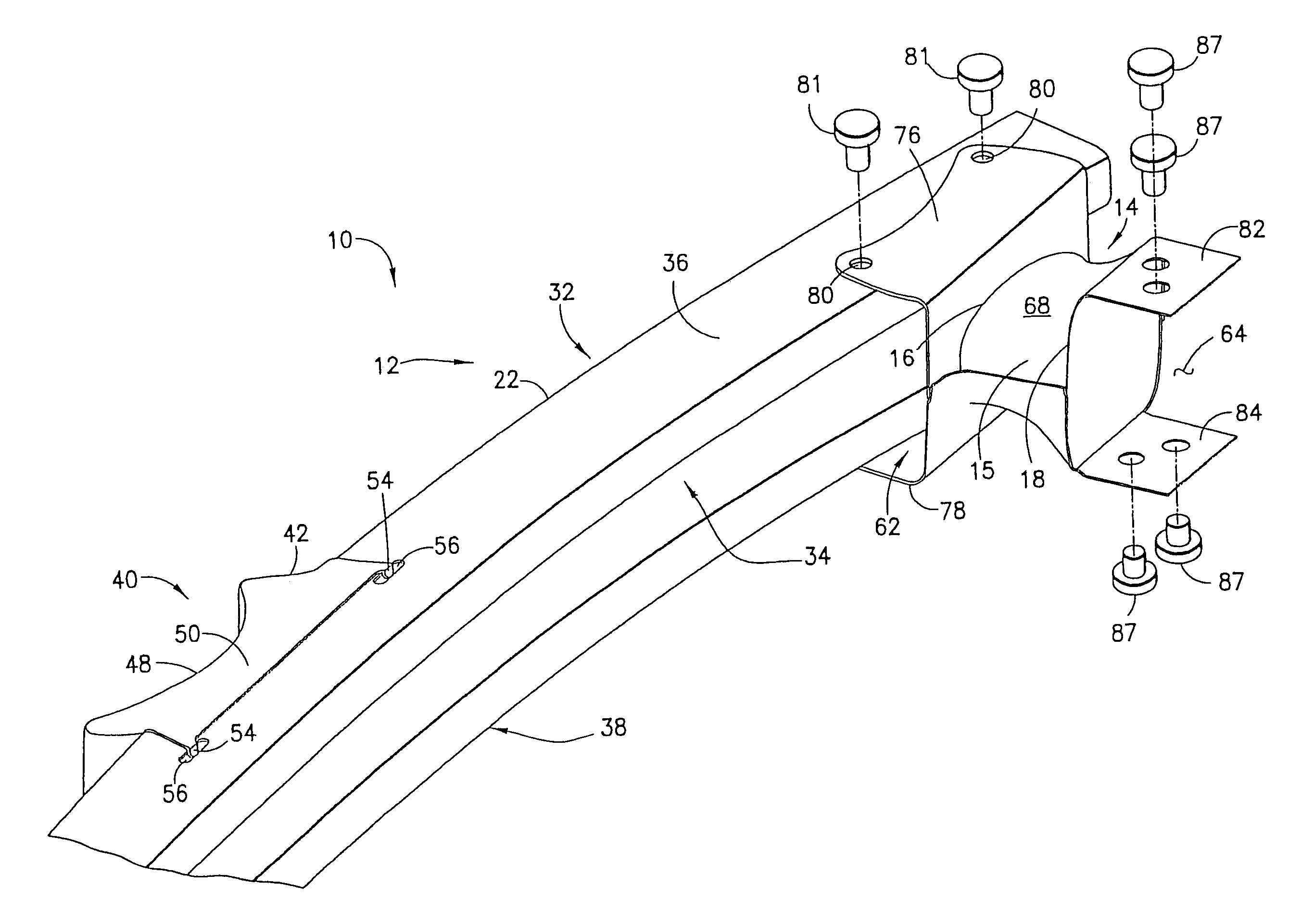
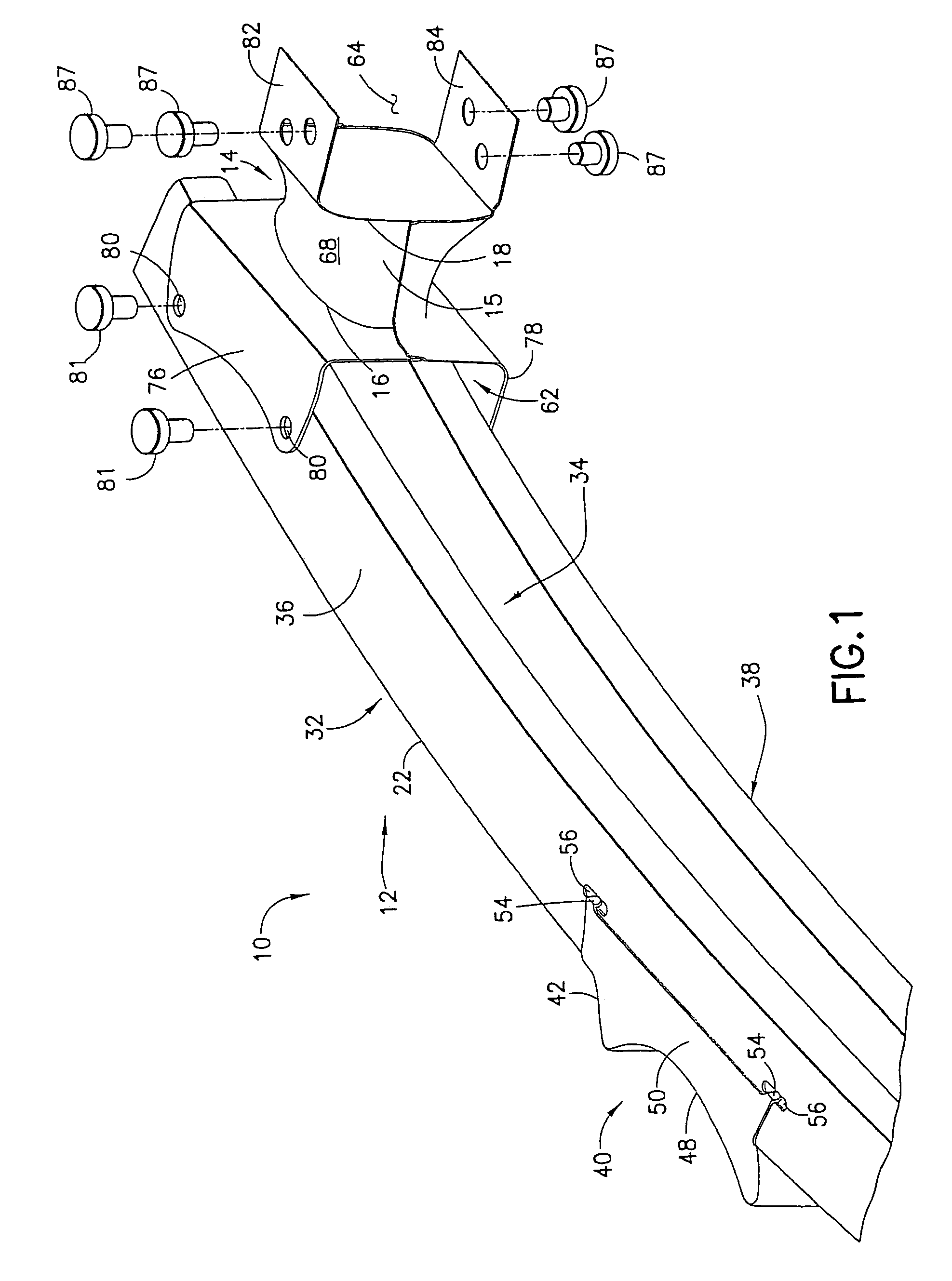
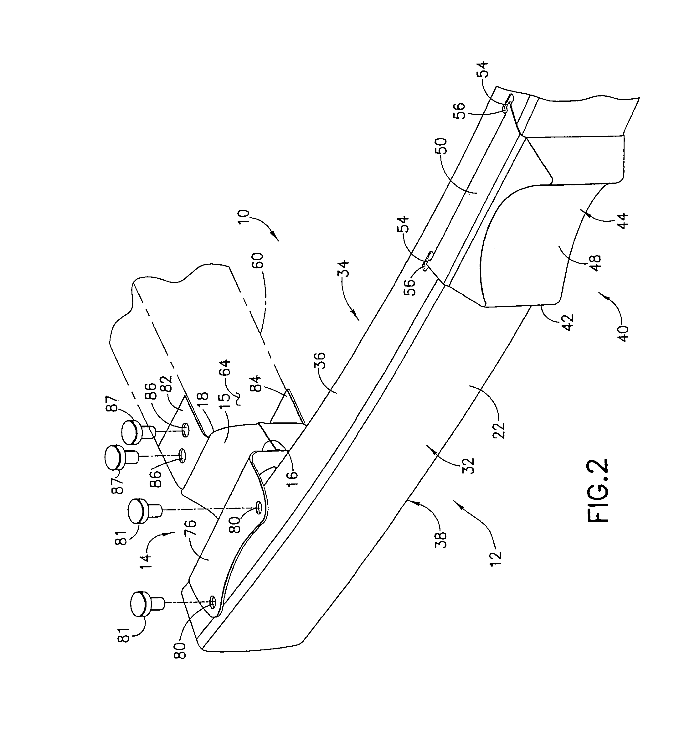
[0045]Referring to FIGS. 1 and 2, a bumper system 10 for a motor vehicle is shown. The bumper system 10 may be provided at the front and / or rear end of a motor vehicle body (not shown). The bumper system 10 is generally comprised of an elongated, preferably curved ...


PUM


Abstract

The bumper system is used on a motor vehicle and generally includes a bumper beam and an energy-absorbing bracket connected to the bumper beam. The bracket includes a hollow energy-absorbing body having a first end and a second end. The bracket body may be saddle-shaped between the first and second ends. The bracket body deforms during a collision involving the motor vehicle. In another embodiment, the bracket body may have a first cross sectional shape at the first end that transitions to a second cross sectional shape at the second end. The second shape may be different from the first shape, or be similar to the first shape, but be, for example, rotated about 90° from the first shape. The first shape may be elongated along a first axis and the second shape elongated along a second axis rotated about 90° from the first axis.

Description

BACKGROUND OF THE INVENTION[0001]1. Field of the Invention[0002]The present invention relates generally to bumpers for motor vehicles and, more specifically, to an energy-absorbing bumper system for a motor vehicle.[0003]2. Description of Related Art[0004]All motor vehicles have bumpers at the front and rear ends of the motor vehicle. Typically, the bumpers include a bumper beam, which provides protection against damage and injury in case of a collision involving the motor vehicle. The bumper beams at the front and rear ends of the motor vehicle body extend transversely with respect to the longitudinal axis of the motor vehicle body. At the front and typically rear ends of the motor vehicle body, the bumper beams are secured to a pair of rails, which connect the bumper beams to the motor vehicle body. The bumper beams are secured to the ends of the rails. The rails extend longitudinally and are spaced apart at the front and rear ends of the motor vehicle body. The bumper beams are t...

Claims


Application Information

Patent Timeline
Patent Type & Authority Patents(United States)
IPC IPC(8): B60R19/24B60R19/34
CPCB60R19/34
Inventor SEKSARIA, DINESH C.
Owner ARCONIC INC
Why Eureka
Try Eureka