Inkjet recording apparatus, ink guide member and purge unit

a technology of ink guide member and purge unit, which is applied in printing and other directions, can solve the problems of deteriorating the cap performance, inability to discharge perfectly, and unsuitable recording state of inkj

Active Publication Date: 2005-07-19
BROTHER KOGYO KK
View PDF7 Cites 16 Cited by
  • Summary
  • Abstract
  • Description
  • Claims
  • Application Information

AI Technical Summary

Benefits of technology

[0014]With such a configuration, the distance between the bottom surface of the sealing portion and the ink guide member is larger in an area near the ink discharge port than in an ar

Problems solved by technology

Due to bubbles or dust entering the inside of a nozzle or due to the viscosity of the ink increased by evaporation of an ink solvent, there is a case in which the ink is not jetted from the nozzle or the jetting state of the ink is not suitable for recording.
In this situation, due to the improper configuration of the cap or the like, the received ink that cannot be di

Method used


Image

  • Inkjet recording apparatus, ink guide member and purge unit
  • Inkjet recording apparatus, ink guide member and purge unit
  • Inkjet recording apparatus, ink guide member and purge unit

Examples


first embodiment

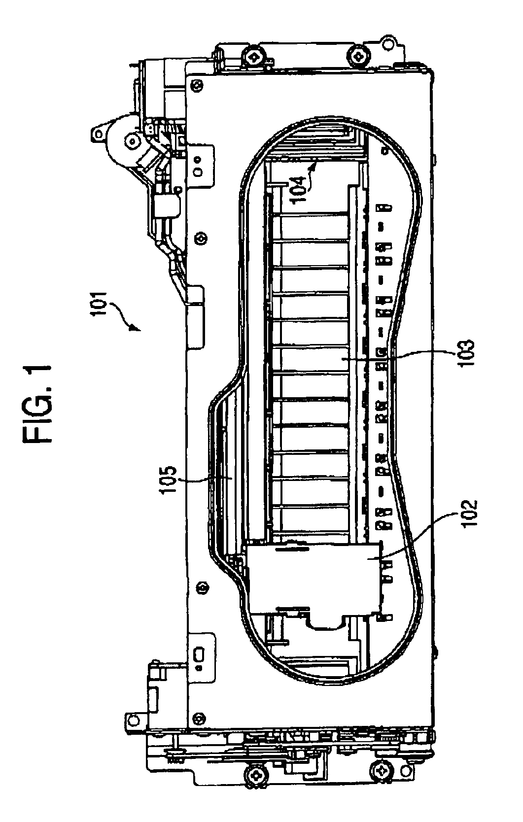
[0055]FIG. 1 is a plan view of a print unit 101 of an inkjet recording apparatus having a purge unit according to the invention. In FIG. 1, the print unit 101 includes a carriage 102, a platen 103 with a rib, and a purge unit 104. The carriage 102 is mounted with a not-shown print head for jetting ink and conducting recording on a recording medium. The recording medium is picked up from a not-shown paper feed tray and carried to the platen 103. The platen 103 keeps the recording medium flat relatively to the print head. The purge unit 104 recovers the jetting conditions of inkjet ports of the print head. The recording medium on which recording has been finished is discharged from the print unit 101 by a not-shown discharge roller.

[0056]The carriage 102 is supported slidably along a horizontal guide shaft 105, and driven by a not-shown carriage motor so as to conduct recording while reciprocating. The purge unit 104 according to the invention is disposed to be lateral to one movable ...

second embodiment

[0096]Now, a second embodiment of the invention will be described below.

[0097]First, a main portion (recording engine E) of an inkjet recording apparatus for jetting ink onto paper to thereby form an image will be described with reference to FIG. 12. The inkjet recording apparatus is provided with a flat platen 202, a carriage guide shaft 204, a carriage 206, a carriage moving mechanism, a paper moving mechanism (not shown) and an inkjet head 210. The flat platen 202 supports paper 200 (see FIG. 13). The carriage guide shaft 204 extends above the platen 202 and in a direction perpendicular to a transporting direction F of the paper 200. The carriage 206 can slide on the carriage guide shaft 204 relatively thereto. The carriage moving mechanism includes a CR motor 208 and so on for moving the carriage 206 along the carriage guide shaft 204. The paper moving mechanism moves the paper 200 in the transporting direction F in accordance with necessity. The inkjet head 210 is fixed to the ...

third embodiment

[0138]Now, description will be given of the configuration of a suction cap of an inkjet recording apparatus according to a third embodiment of the invention. In FIGS. 26-30 and 31A-31C, members and portions having the same functions as those in the second embodiment are denoted by the same reference numbers correspondingly, and description thereof will be omitted accordingly. In this embodiment, the foot portions 11a of the ink guide member 10 are omitted. Alternatively, as shown in FIG. 29, a support portion 9 for supporting the ink guide member 10 is integrally provided under the protrusion portion 7 of the cap member 2 by molding. The distance between the ink guide member 10 and the bottom surface 6 of the cap member 2 is defined by the support portion 9. In this embodiment, the support portion 9 is provided substantially in parallel with the contact portion 5 of the cap member 2 so that the distance from the bottom surface 6 increases as the distance from the ink discharge port ...


PUM


Abstract

In an inkjet recording apparatus, a suction channel is defined between a concave groove-like channel of an ink guide member and a cap member. An ink discharge port is open to the suction channel while the suction channel communicates with the atmosphere through a plurality of communication holes. The distance between a bottom surface of the cap member and a surface of the concave groove-like channel facing the bottom surface is reduced in accordance with the distance from the ink discharge port. The ink discharge port is entirely covered with one longitudinal end portion of the ink guide member. The horizontal sectional area of each communication hole increases in accordance with the distance from the ink discharge port.

Description

BACKGROUND OF THE INVENTION[0001]1. Field of the Invention[0002]The present invention relates to an ink jet recording apparatus, an ink guide member in the inkjet recording apparatus, a suction cap engaged with the ink guide member, and a purge unit having the suction cap.[0003]2. Description of the Related Art[0004]Conventionally, there is known an inkjet recording apparatus that jets out ink from an inkjet head to thereby conduct printing. A large number of nozzles for jetting ink are formed in the inkjet head. Due to bubbles or dust entering the inside of a nozzle or due to the viscosity of the ink increased by evaporation of an ink solvent, there is a case in which the ink is not jetted from the nozzle or the jetting state of the ink is not suitable for recording. Therefore, an ink jet recovery process is carried out to remove such factors in failure in ink jet.[0005]As a unit for carrying out such an ink jet recovery process, there is provided a unit including a cap capable of ...

Claims


Application Information

Patent Timeline
IPC IPC(8): B41J2/165
CPCB41J2/16508
Inventor UMEDA, TAKAICHIROOGAWA, MIKIOYAZAWA, HIROAKISHIOHARA, YUKIO
Owner BROTHER KOGYO KK
Why Eureka
Try Eureka