
Combination structure of a motor

a technology of combination structure and motor, which is applied in the direction of record information storage, magnetic circuit shape/form/construction, instruments, etc., can solve the problems of prior art motors that are unsuitable for small-sized electronic devices such as thin optical disk drives, and achieve the effect of avoiding an increase in the axial height of the motor

Inactive Publication Date: 2005-07-19
SUNONWEALTH ELECTRIC MACHINE IND
View PDF3 Cites 10 Cited by
  • Summary
  • Abstract
  • Description
  • Claims
  • Application Information

AI Technical Summary

Benefits of technology

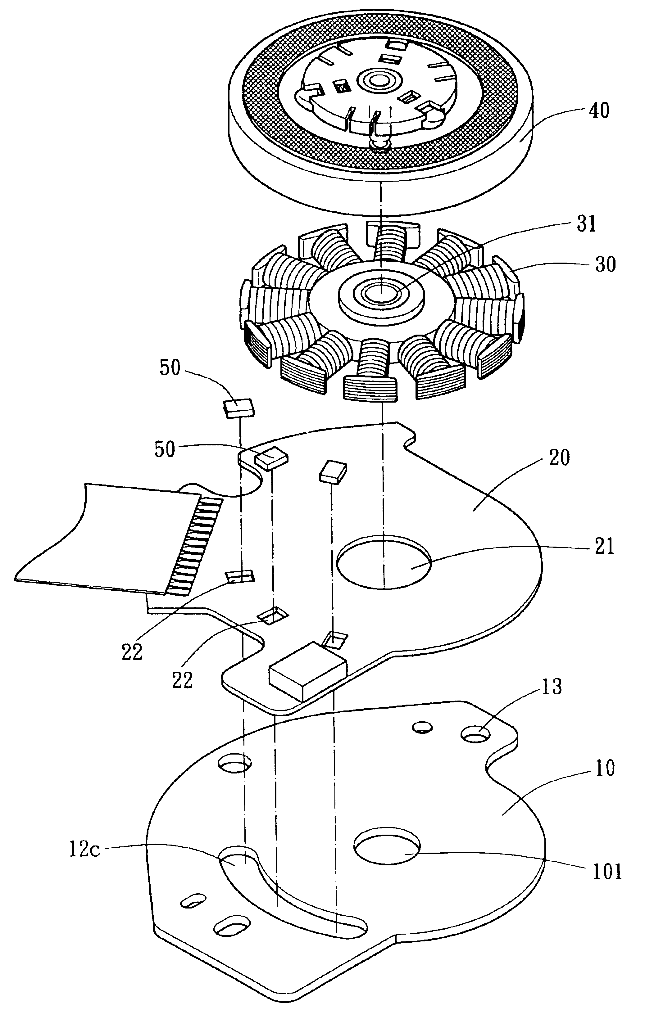
[0007]A main objective of the present invention is to provide a combination structure of a motor which has at least one assembly hole on each of the base board and the printed circuit board to contain the sensing unit, so that the sensing unit can avoid an increase of the axial height of the motor.
[0008]Another objective of the present invention is to provide a combination structure of a motor which has at least one assembly hole on each of the base board and the printed circuit board to contain the sensing unit at a predetermined position so the that sensing unit is easily mounted.
[0009]In order to achieve the above-mentioned objectives, the present invention includes a base board, a printed circuit board and at least one sensing unit. The base board is used for placing a stator and a rotor and has at least one first assembly hole. The printed circuit board is attached to the base board and has at least one second assembly hole. The sensing unit is used to sense a magnet of the rotor. The second assembly hole of the printed circuit board is disposed corresponding to the first assembly hole of the base board for commonly containing the sensing unit so that an axial height of the motor is decreased.

Problems solved by technology

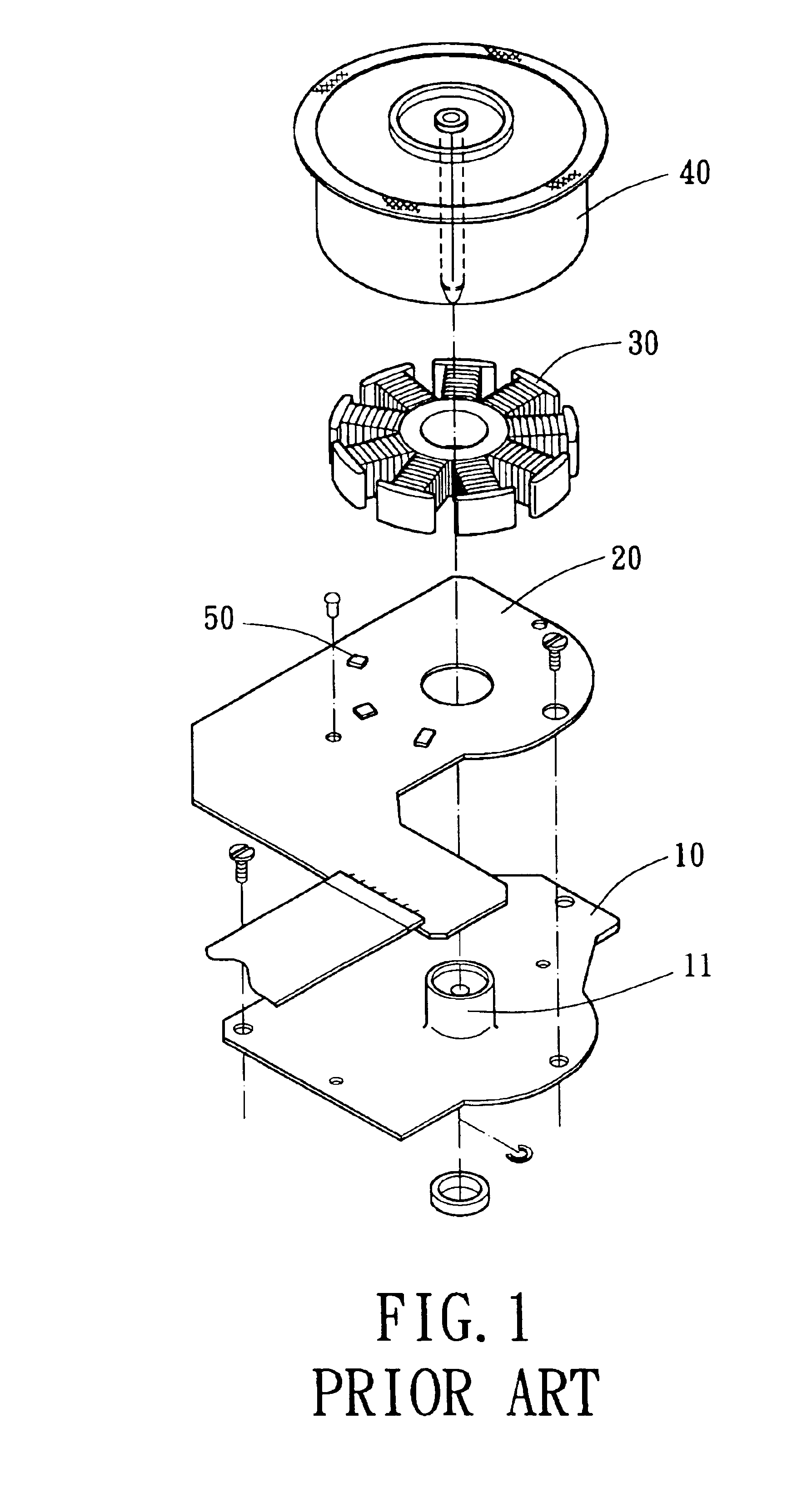
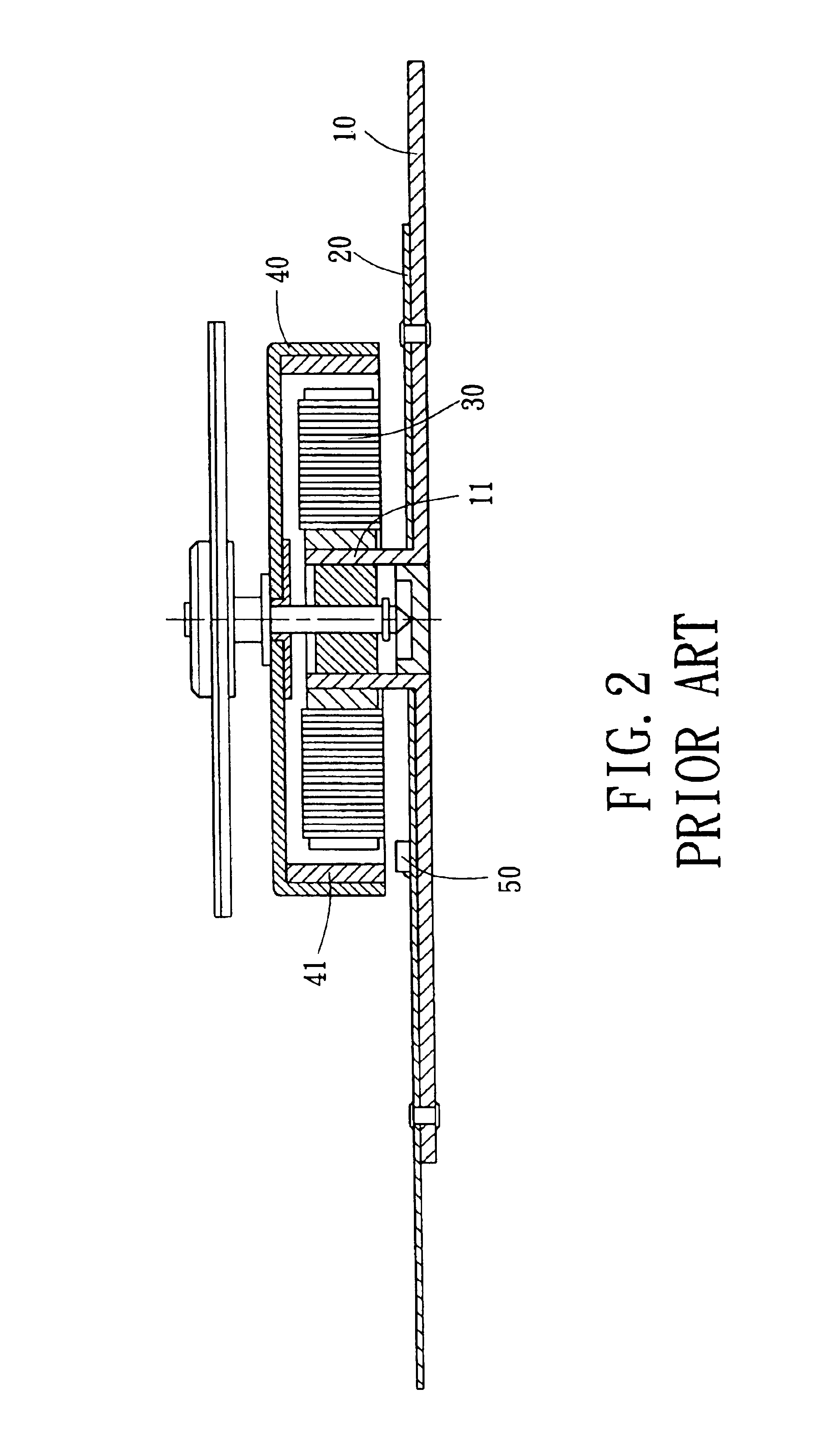
Hence, the sensing unit 50 occupies space and increases an axial height of the prior art motor, which causes the prior art motor to be unsuitable for a small size electronic device, such as a thin optical disk drive.

Method used


Image

  • Combination structure of a motor
  • Combination structure of a motor
  • Combination structure of a motor

Examples


Embodiment Construction

[0022]FIG. 3 is an exploded drawing of a motor structure according to a first embodiment of the present invention. FIG. 4 is a top view drawing of the motor structure according to the first embodiment of the present invention. FIG. 5 is a cross sectional drawing, taken along line 5—5, in FIG. 4 according to the present invention. FIG. 6 is an enlarged view in FIG. 5 according to the present invention. FIG. 7 is an enlarged view of a motor structure according to a second embodiment of the present invention. FIG. 8 is an enlarged view of a motor structure according to a third embodiment of the present invention. FIG. 9 is an enlarged view of a motor structure according to a fourth embodiment of the present invention. FIG. 10 is an enlarged view of a motor structure according to a fifth embodiment of the present invention. FIG. 11 is an exploded view of a motor structure according to a sixth embodiment of the present invention.

[0023]Some elements of the motor of the present invention a...


PUM

PropertyMeasurementUnit
combination structureaaaaaaaaaa
structureaaaaaaaaaa
dimensionsaaaaaaaaaa

Abstract

A combination structure of a motor has a base board, a printed circuit board and at least one sensing unit. The base board is used for placing a stator and a rotor and has at least one first assembly hole. The printed circuit board is connected to the base board and has at least one second assembly hole. The sensing unit is used for sensing a magnet of the rotor. The second assembly hole of the printed circuit board is placed corresponding to the first assembly hole of the base board for commonly containing the sensing unit so that an axial height of the motor is decreased.

Description

BACKGROUND OF THE INVENTION[0001]1. Field of the Invention[0002]The present invention is related to a combination structure of a motor and, more particularly, to a combination structure of a motor that has at least one assembly hole on each of a base board and a printed circuit board for containing at lease one sensing unit to decrease an axial height of the combination structure.[0003]2. Description of the Related Art[0004]Referring to FIGS. 1 and 2, a prior art motor structure, such as Taiwanese patent publication No.456667 “Combination Structure for DC brushless motor”, includes a base board 10, a printed circuit board 20, a stator 30 and a rotor 40. The base board 10 has an axle tube adapted to assemble the printed circuit board 20, the stator 30 and the rotor 40. At least one sensing unit 50 is welded on an upper surface of the printed circuit board 20. The sensing unit 50 is placed below an annular magnet 41 of the rotor 40 and is used for sensing the annular magnet 41. The pr...

Claims


Application Information

Patent Timeline
Patent Type & Authority Patents(United States)
IPC IPC(8): H02K29/06H02K29/08H02K1/18
CPCH02K1/187H02K29/08H02K2211/03
Inventor HORNG, ALEXHONG, YIN-RONG
Owner SUNONWEALTH ELECTRIC MACHINE IND
Learn More