High-voltage discharge lamp lighting apparatus, high-voltage discharge lamp apparatus, and floodlight projector apparatus

a technology lamp body, which is applied in the direction of cathode-ray/electron beam tube circuit elements, instruments, and coupling device connections, etc. it can solve the problems of increased replacement cost of high-voltage discharge lamp, danger of electric shock, etc., and achieves small lamp attachment space, reduces the number of contacts and connecting parts, and improves the operability of attachmen

Inactive Publication Date: 2005-07-19
HARISON TOSHIBA LIGHTING CORP
View PDF6 Cites 9 Cited by
  • Summary
  • Abstract
  • Description
  • Claims
  • Application Information

AI Technical Summary

Benefits of technology

[0016]Further, a second object of the present invention is to provide a high-voltage discharge lamp lighting apparatus, a high-voltage discharge lamp apparatus, and a floodlight projector apparatus which are capable of easily connecting the cap portion to the socket portion by a small number of connecting pieces as much as possible and are capable of reducing replacement costs of the high-voltage discharge lamp portion upon replacing the high-voltage discharge lamp.DISCLOSURE OF INVENTION
[0072]According to the tenth and eleventh inventions, in the high-voltage discharge lamp apparatus and the floodlight projector apparatus. The numbers of contacts and connecting pieces are reduced when the high-voltage discharge lamp or the floodlight projector is attached to the high-voltage discharge lamp lighting apparatus for the electric connection. Advantageously, the attachment operability is improved and the lamp attachment space is small.

Problems solved by technology

When the operator touches the connecting pieces 75a and 75b in this state, there is a danger for getting an electric shock.
However, the conventional arts (1) and (2) have problems that the cap portion and the socket portion need four connecting pieces, respectively, the shape of the cap portion becomes large, and the high-voltage pulse transformer must be replaced together because the cap portion includes at least the high-voltage pulse transformer upon replacing the high-voltage discharge lamp and the replacement costs of high-voltage discharge lamp are increased.

Method used


Image

  • High-voltage discharge lamp lighting apparatus, high-voltage discharge lamp apparatus, and floodlight projector apparatus
  • High-voltage discharge lamp lighting apparatus, high-voltage discharge lamp apparatus, and floodlight projector apparatus
  • High-voltage discharge lamp lighting apparatus, high-voltage discharge lamp apparatus, and floodlight projector apparatus

Examples


first embodiment

[0090]Hereinbelow, the present invention will be described with reference to FIGS. 1, 2A, and 2B.

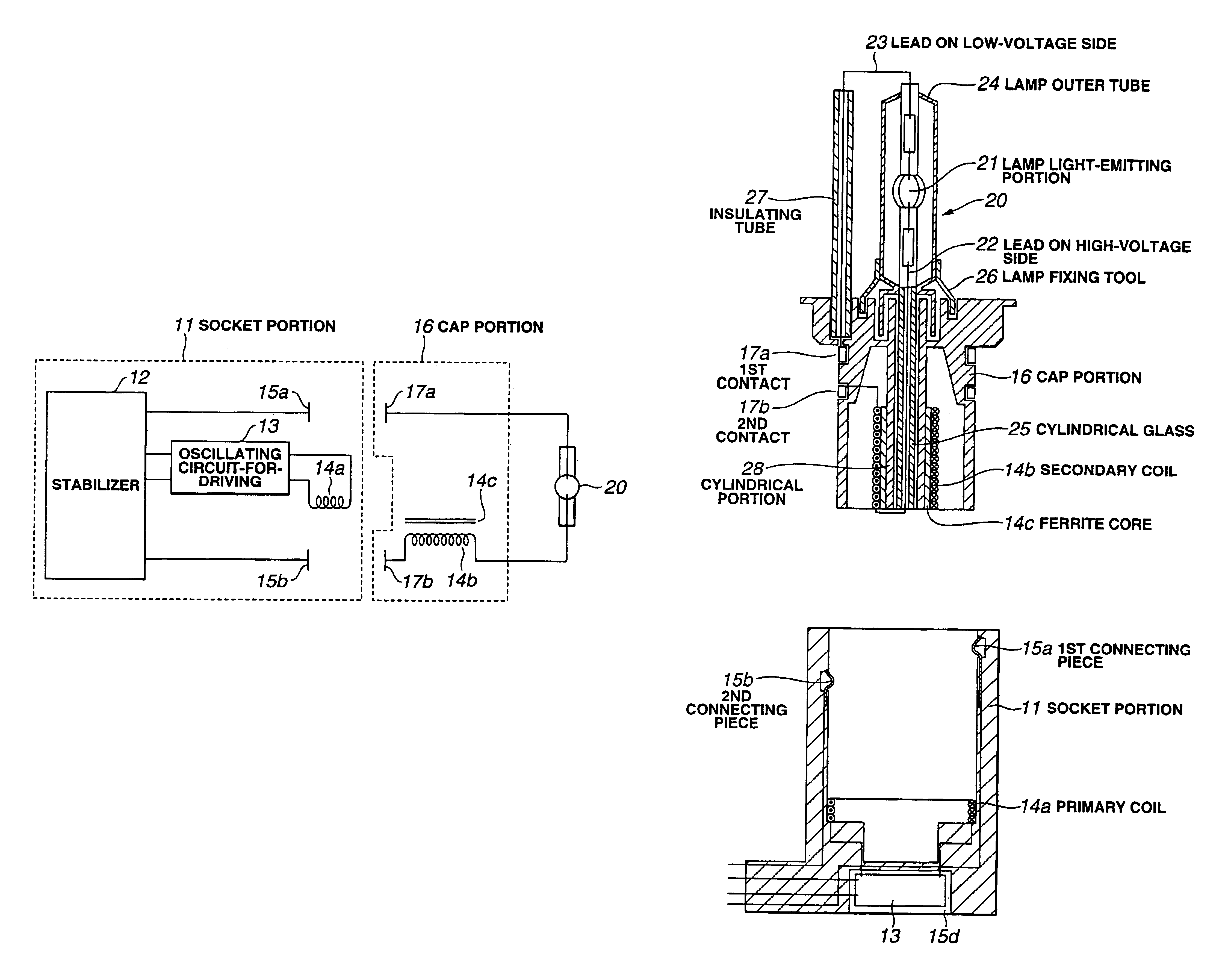
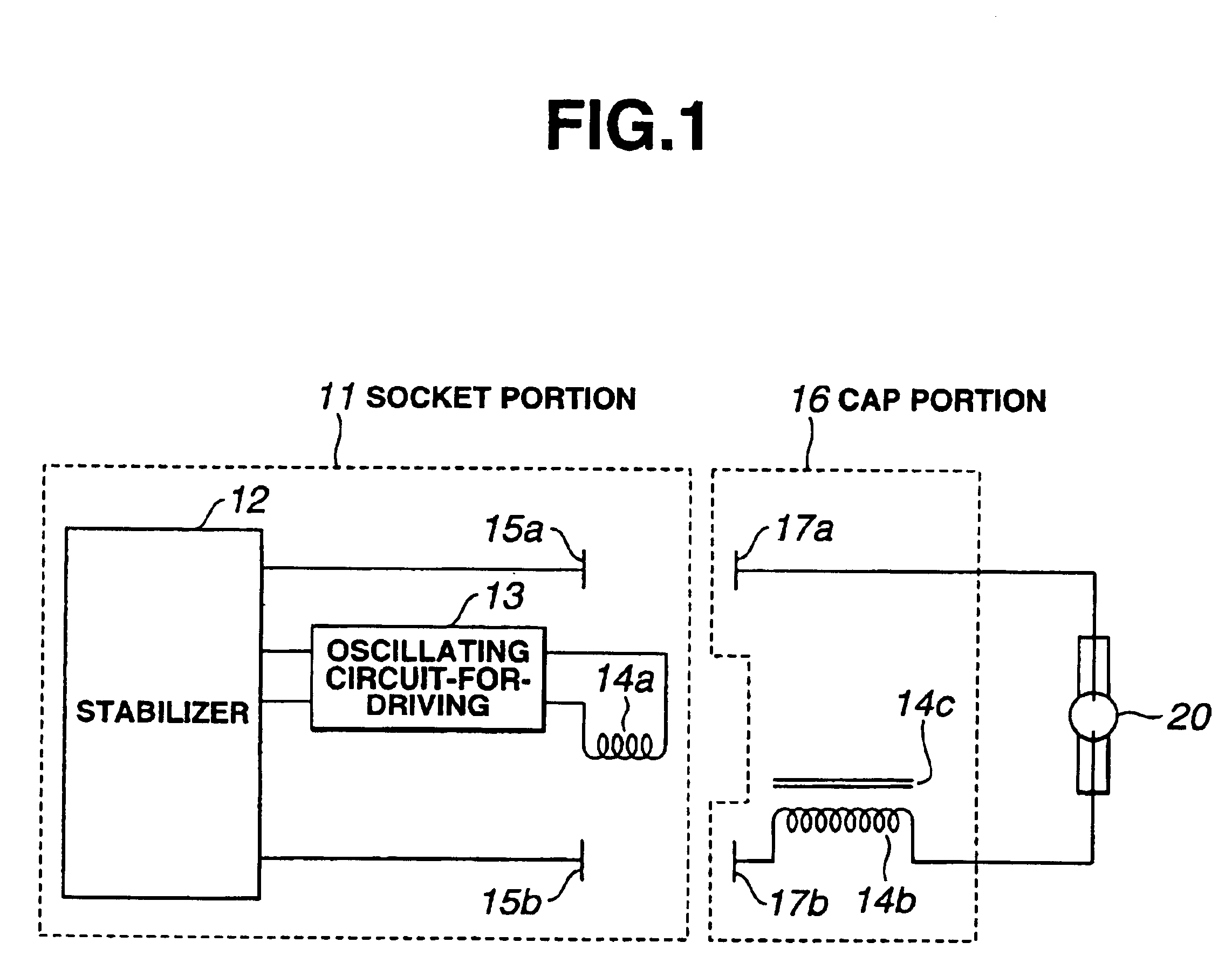
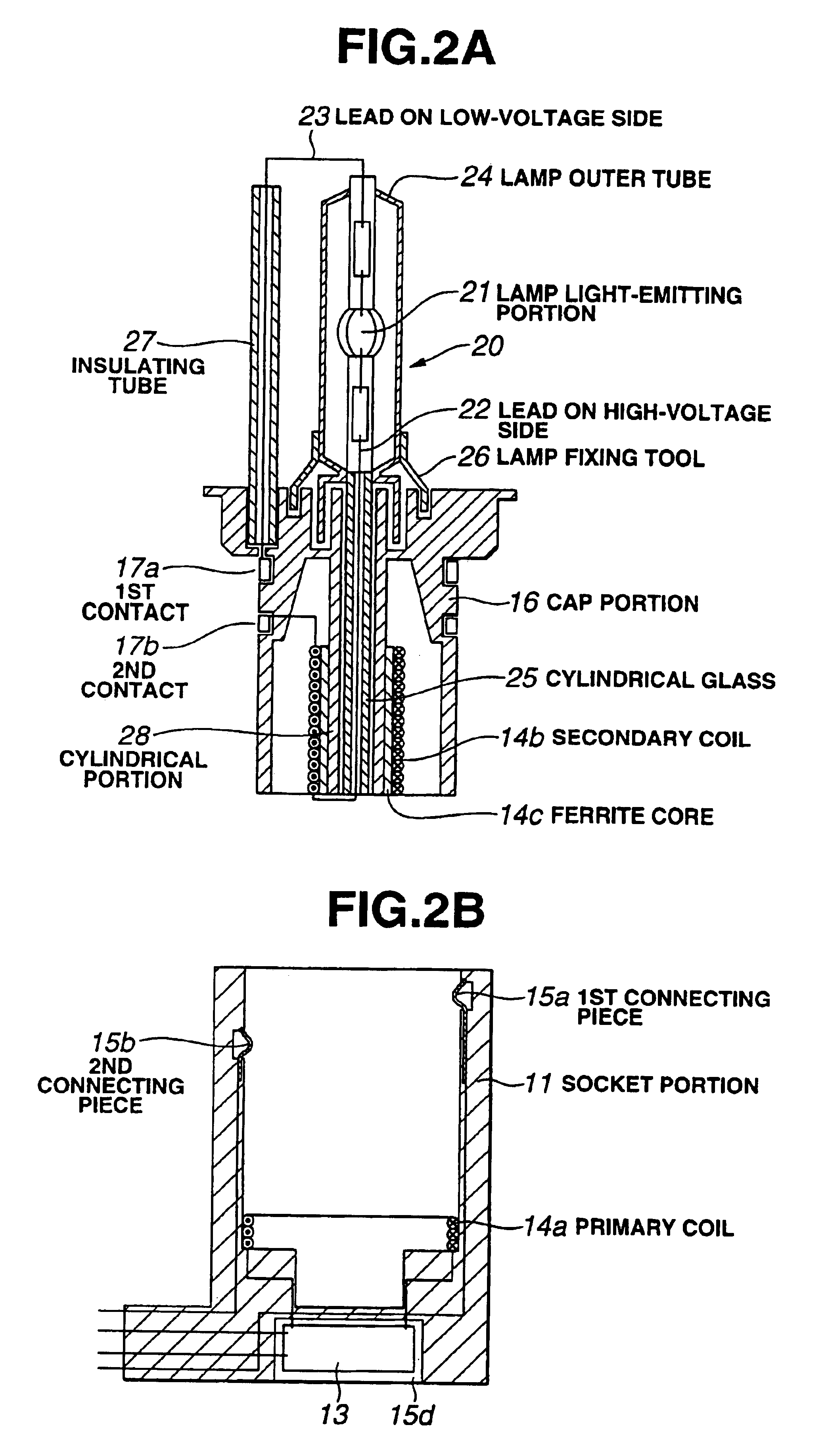
[0091]FIG. 1 is a block diagram of showing the structure of a high-voltage discharge lamp lighting apparatus according to the first embodiment of the present invention, FIG. 2A is a sectional view for explaining the structure of a cap portion used for the high-voltage discharge lamp lighting apparatus according to the first embodiment of the present invention, and FIG. 2B is a sectional view for explaining the structure of a socket portion to which the cap portion shown in FIG. 2A is fit and attached. Here, a description is given of a lighting apparatus of a headlight lamp for automobile as the high-voltage discharge lamp lighting apparatus of the present invention.

[0092]The high-voltage discharge lamp lighting apparatus shown in FIG. 1 is in a state before fitting and attaching the cap portion 16 to the socket portion 11. By fitting and attaching the cap portion 16 to the socket portion...

second embodiment

[0124]Referring to FIG. 3A, according to the present invention, the socket portion 11 comprises: the stabilizer 12; the oscillating circuit-for-driving 13 which generates a high-frequency oscillating voltage based on the DC power voltage from the stabilizer 12; the primary coil 14a and the ferrite core 14c of the high-voltage pulse transformer 14 to which the high-frequency oscillating voltage generated by the oscillating circuit-for-driving 13 is supplied. Further, the socket portion 11 has the first connecting piece 15a and the second connecting piece 15b which output the power voltage necessary for maintaining the lighting operation from the stabilizer 12.

[0125]The cap portion 16 comprises: the secondary coil 14b of the high-voltage pulse transformer 14; the second contact 17b for connection to one electrode of the high-voltage discharge lamp 20 via the secondary coil 14b; and the first contact 17a for connection to another electrode of the high-voltage discharge lamp 20.

[0126]Th...

third embodiment

[0138]Referring to FIG. 3B, the high-voltage discharge lamp lighting apparatus comprises the cap portion 16 and the socket portion 11 as shown in FIGS. 4A and 4B. Referring to FIGS. 4A and 4B, the same portions as those shown in FIGS. 2A and 2B are designated by the same reference numerals and a detailed description is omitted.

[0139]Referring to FIG. 4B, the socket portion 11 comprises the primary coil 14a, the secondary coil 14b, and the magnetic core 14c of the high-voltage pulse transformer 14. One output terminal from the stabilzier 12 is connected to the first connecting piece 15a and a terminated end of the primary coil 14a is connected to the third connecting piece 15c in the socket portion 11. A terminated end of the secondary coil 14b is connected to the connecting piece 15b′ on the high-voltage side in the center of the bottom portion of the socket portion 11.

[0140]Referring to FIG. 4A, a first contact 17a is arranged to the cap portion 16 like strips so as to connect the...


PUM


Abstract

A high-voltage discharge lamp lighting apparatus has a stabilizer which supplies a power voltage used for maintaining the lighting operation to a high-voltage discharge lamp, and an ignitor circuit having an oscillating circuit-for-driving in which a start pulse generates upon starting the lighting operation of the high-voltage discharge lamp, and high-voltage pulse generating transformers which increase a voltage of the start pulse. Further, the high-voltage discharge lamp lighting apparatus includes a cap portion to which the high-voltage discharge lamp is attached and held, including a part of the high-voltage pulse generating transformers of the ignitor circuit, and a socket portion to which the cap portion is attached and is fit, including at least the oscillating circuit-for-driving in the ignitor circuit and a portion of the high-voltage pulse generating transformers except for a part included in the cap portion.

Description

[0001]This application claims benefit of Japanese Application No. 2001-264812 filed in Japan on Aug. 31, 2001, the contents of which are incorporated by this reference.BACKGROUND OF THE INVENTION[0002]1. Field of the Invention[0003]The present invention relates to a high-voltage discharge lamp lighting apparatus which is formed by integrating a high-voltage pulse generating transformer of a lighting apparatus to a lamp base such as a high-voltage discharge lamp and a floodlight projector, and a high-voltage discharge lamp apparatus and a floodlight projector apparatus using the lighting apparatus.[0004]2. Description of the Related Art[0005]Conventionally, a headlight lamp for automobile, e.g., a metal halide lamp high-voltage discharge lamp uses a high-voltage discharge lamp apparatus which is controlled such that high power is turned on upon starting and fast starting operation is obtained by using a stabilizer and a high-voltage generating apparatus (hereinafter, referred to as a...

Claims


Application Information

Patent Timeline
Patent Type & Authority Patents(United States)
IPC IPC(8): H01R33/09H01R33/05H05B41/02H05B41/04H05B41/28H05B41/00H05B41/288H01R13/53H01J5/54
CPCH01J5/54H01R33/09H05B41/02H05B41/042H05B41/2881H01R13/53Y02B20/19Y02B20/204Y02B20/00H05B41/18
Inventor KIKA, MANABU
Owner HARISON TOSHIBA LIGHTING CORP
Why Eureka
Try Eureka