Methods to control the droop when powering dual mode processors and associated circuits

a dual-mode processor and associated circuit technology, applied in the direction of electric variable regulation, process and machine control, instruments, etc., can solve the problems of significant lower processor current, extra battery life, and known droop method not providing relative equal droop for the different operation modes

Inactive Publication Date: 2005-07-19
INTERSIL CORP
View PDF13 Cites 68 Cited by
  • Summary
  • Abstract
  • Description
  • Claims
  • Application Information

AI Technical Summary

Benefits of technology

[0041]FIG. 7 is a schematic drawing of a DC/DC converter with a constant droop and voltage control.
[0042]FIG. 8 is a graphical comparison of the operation of the circuit of FIG. 6 and FIG. 7 with a prior art under performance and battery operation.
[0043]FIG. 9 is a schematic drawing of a DC/DC converter with a dual control droop circuit under frequency set offset.
[0044]FIG. 1

Problems solved by technology

The additional power reduction may be about 10% and results in extra battery life.
The known droop method does not provide relatively equal droop for the different operation modes because the gain in the current feedback loop is constant.
In this case, the processor current is significantly lower, the droo

Method used


Image

  • Methods to control the droop when powering dual mode processors and associated circuits
  • Methods to control the droop when powering dual mode processors and associated circuits
  • Methods to control the droop when powering dual mode processors and associated circuits

Examples


Embodiment Construction

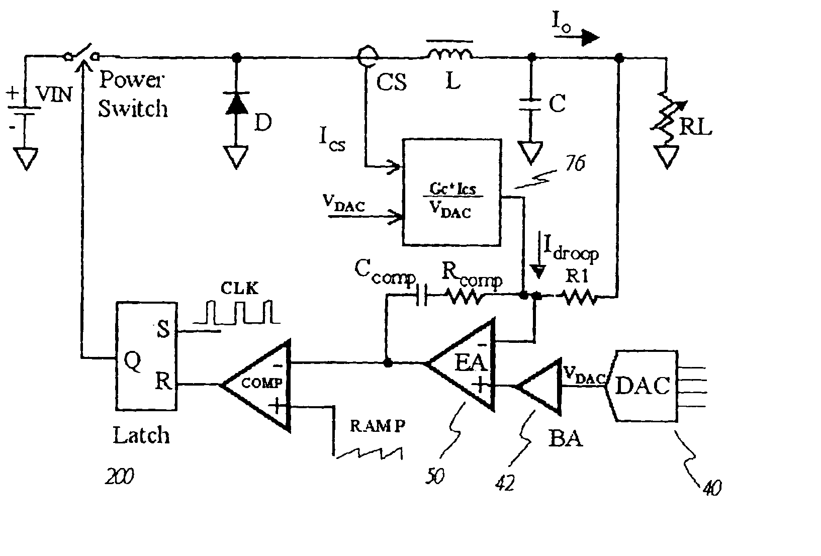
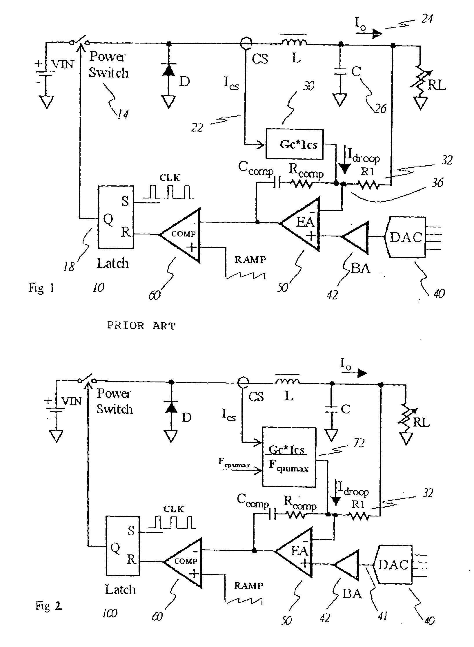
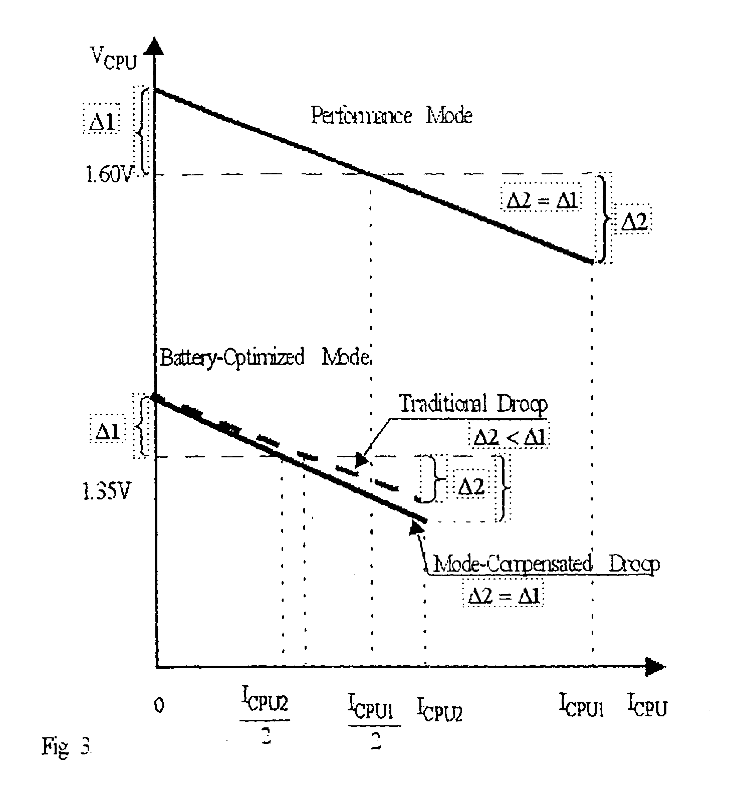
[0047]One significant attribute of this invention is an adjustable droop control that is achieved by varying the gain in the current feedback loop. The current loop gain is made to be inversely proportional to the processor maximum operating frequency. This effectively changes the slope of the converter's load line in accordance with the operating mode of the processor. The sensed current signal, which can be either inductor current, or switch current, or diode (or synchronous switch) current, is multiplied by the signal inversely proportional to the processor maximum operating frequency. A resulting current product signal is summed with the voltage feedback signal at the input of the voltage-loop error amplifier.

[0048]FIG. 2 illustrates one implementation of the new method to provide the droop. The converter 100 has a DAC 40 that receives a code associated with desired processor operating voltage and sets the reference voltage on its output 41. The reference voltage (VDAC) is boost...


PUM


Abstract

A DC/DC converter 100 has a DAC 40 that receives a code associated with desired processor operating voltage and sets the reference voltage on its output 41. The reference voltage (VDAC) is boosted by the buffer amplifier 42 to center the droop along the median load. A sensed current signal ICS 22 is proportional to the load current Io 24 and can be either inductor current, or switch current, or diode (or synchronous switch) current. In all cases it is scaled down by the factor of gain Gc. A droop control feedback circuit includes an error amplifier 50. It has two inputs. In one embodiment the gain of the converter is by a signal inversely proportional to the processor clock frequency FCPU max and transformed to the current IDROOP 32 that creates the voltage drop across the resistor R1. The other input is coupled to the buffer amplifier output. As a result, the output voltage of the converter 50 is inversely proportionally to the load current and is invariant to the processor clock frequency changes associated with the processor mode switchover. Other embodiments modify the gain of the error amplifier, or offset the gain and hold the amount of droop constant.

Description

CROSS-REFERENCE TO RELATED APPLICATIONS[0001]This application is a divisional application of U.S. patent application Ser. No. 09 / 791,509, filed on Feb. 22, 2001, now U.S. Pat. No. 6,680,604, which claims the benefit of U.S. Provisional Patent Application Ser. No. 60 / 192,383 filed Mar. 27, 2000.BACKGROUND OF THE INVENTIONUse of Dual Mode Processors and Droop in Mobile Computer Applications[0002]Modern notebook computers employ advanced processors with high clock rates that place higher demand on the battery life and impose higher thermal stresses on to the circuit components. To enable systems with higher performance without compromising battery life, dual mode processors were introduced. These processors operate on higher clock rates and higher voltage when the notebook is powered from the wall adapter (so-called “performance mode”). When battery power is used, the operating voltage and the clock frequency are simultaneously scaled down to reduce the consumed power without greatly c...

Claims


Application Information

Patent Timeline
IPC IPC(8): G06F1/32G06F1/26
CPCG06F1/26G06F1/32G06F1/324Y02B60/1217Y02D10/00
Inventor MURATOV, VOLODYMYR A.COLETTA, MICHAELWIKTOR, WLODZIMERZ S.
Owner INTERSIL CORP
Why Eureka
Try Eureka