Light calibration device for use in low level light imaging systems

a technology of light calibration and imaging system, which is applied in the field of calibration techniques, can solve the problems of varied image capture conditions, incongruity of image capture accuracy at these low light levels with conventional imaging systems, and numerous challenges of imaging applications, so as to achieve the effect of assessing the accuracy of the imaging system and its absolute imaging characteristics

Inactive Publication Date: 2005-07-19
XENOGEN CORP
View PDF25 Cites 59 Cited by
  • Summary
  • Abstract
  • Description
  • Claims
  • Application Information

AI Technical Summary

Benefits of technology

[0005]The present invention relates to systems and methods for calibrating a low-level light imaging system. Techniques described herein employ a light calibration device that is placed within a low level light imaging box to calibrate the system and its constituent imaging components such as the camera, imaging box and lens. The calibration device comprises an array of low-emission light supplies having a known emission. In one embodiment, the array of low-emission light supplies are Lambertian surface emitters with a surface radiance of between about 103 to about 1010 photons / second / centimeter squared / steradian. By taking an exposure of one or more of the low-power light sources, and comparing the processed result with the known emission, the accuracy of the imaging system and its absolute imaging characteristics may be assessed and verified.

Problems solved by technology

Such imaging applications present numerous challenges.
One particular obstacle for these imaging systems is the diverse image capture conditions that they are required to perform under.
The accuracy of image capture at these low light levels is often inconsistent with conventional imaging systems.
For example, inconsistency between different camera designs may affect the accuracy between different imaging systems.
Alternately, drift introduced in the readout of a camera over its operational life may introduce inaccuracies that affect the repeatability of imaging within the same system over time.
Irregularities between image capture trials on the order of several photons may contaminate data; thereby compromising the ability for an imaging system to provide absolute and repeatable results.
Since the cameras employ considerable sensitivity at low light levels, conventional techniques for calibration often produce too much light, saturate the cameras, and are unsuitable.

Method used


Image

  • Light calibration device for use in low level light imaging systems
  • Light calibration device for use in low level light imaging systems
  • Light calibration device for use in low level light imaging systems

Examples


Embodiment Construction

[0017]In the following detailed description of the present invention, numerous specific embodiments are set forth in order to provide a thorough understanding of the invention. However, as will be apparent to those skilled in the art, the present invention may be practiced without these specific details or by using alternate elements or processes. In other instances well known processes, components, and designs have not been described in detail so as not to unnecessarily obscure aspects of the present invention.

I. Imaging System

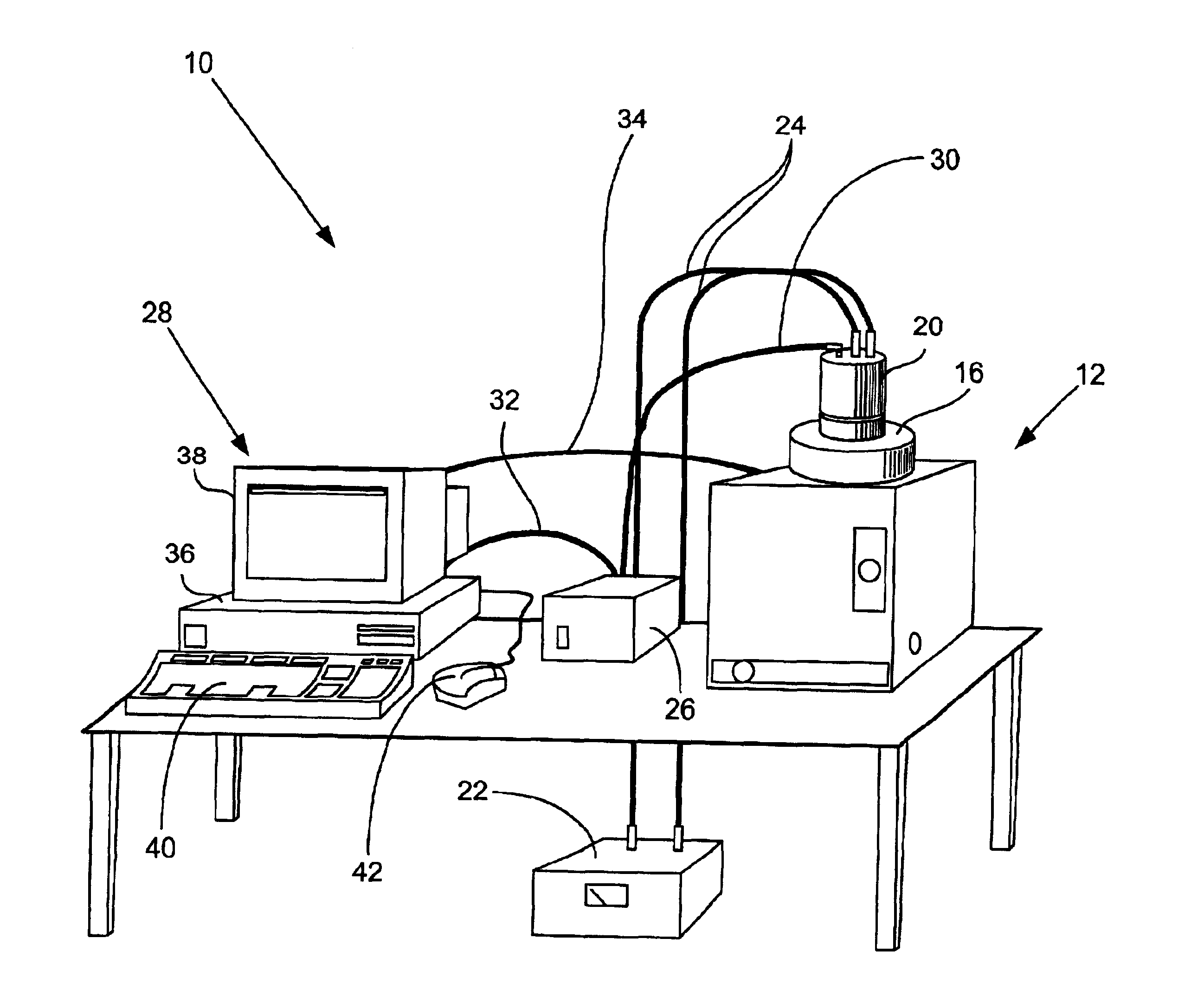
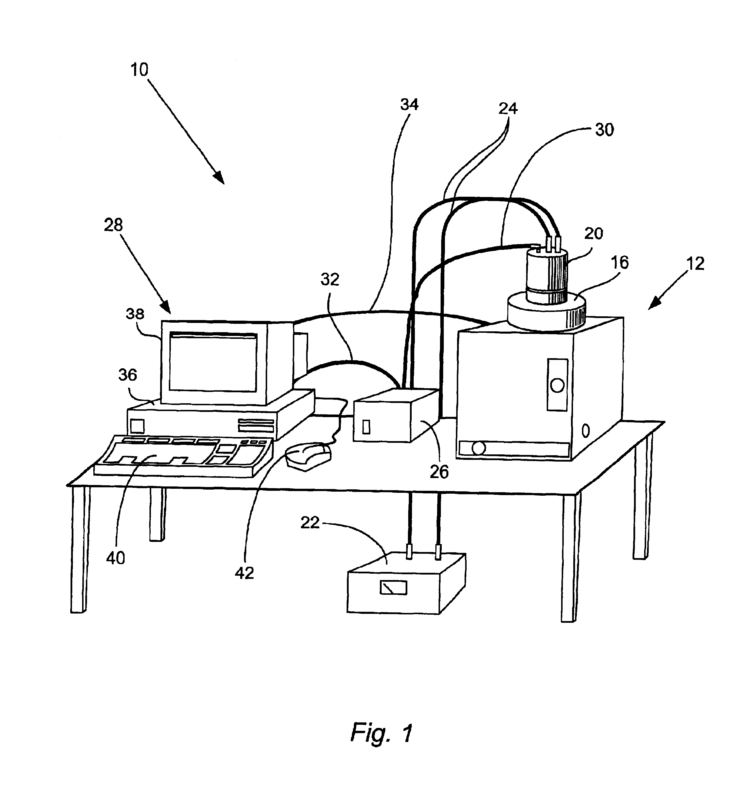
[0018]In one aspect, the present invention relates to imaging systems for capturing an image of a low intensity light source. FIG. 1 illustrates an imaging system 10 configured to capture photographic and luminescence images in accordance with one embodiment of the present invention. Imaging system 10 may be used for imaging a low intensity light source, such as luminescence from luciferase-expressing cells, fluorescence from fluorescing molecules, and the li...


PUM

PropertyMeasurementUnit
diameteraaaaaaaaaa
diametersaaaaaaaaaa
diametersaaaaaaaaaa

Abstract

The invention describes systems and methods for calibrating a low-level light imaging system. Techniques described herein employ a light calibration device that is placed within a low level light imaging box to calibrate the system and its constituent components such as the camera and processing system. The calibration device comprises an array of low-power light supplies each having a known emission. By taking an image of each low-power light supply, and comparing the processed result with the known emission, the accuracy of the imaging system and its absolute imaging characteristics may be assessed and verified.

Description

FIELD OF THE INVENTION[0001]The present invention relates generally to calibration techniques. More specifically, the present invention relates to calibration techniques suitable for use in low level light imaging systems capable of imaging low intensity light sources.BACKGROUND OF THE INVENTION[0002]One new and specialized type of imaging involves the capture of low intensity light—often on the order of only tens to hundreds of photons—from a light emitting sample. The source of the light indicates portions of the sample, such as traced molecules in a particular portion of a laboratory mammal, where an activity of interest may be taking place. For example, specialized in-vivo imaging applications may include analysis of one or more representations of emissions from internal portions of a specimen superimposed on a photographic representation of the specimen. The luminescence representation indicates portions of the specimen where an activity of interest may be taking place. The pho...

Claims


Application Information

Patent Timeline
Patent Type & Authority Patents(United States)
IPC IPC(8): G01N21/27G01N21/25G01J1/00G01J1/08
CPCG01J1/08G01N21/278
Inventor NELSON, MICHAEL B.RICE, BRADLEYBATES, BRIAN R.BEEMAN, BARTON V.
Owner XENOGEN CORP
Why Eureka
Try Eureka