Optical device and method of manufacture of the same, display device, electronic device, and detection device

Inactive Publication Date: 2005-07-19
SEIKO EPSON CORP
View PDF15 Cites 8 Cited by
  • Summary
  • Abstract
  • Description
  • Claims
  • Application Information

AI Technical Summary

Benefits of technology

[0030]With the above-described electronic device, it is possible to anticipate improvement of the produ

Problems solved by technology

However, with the above-described method of manufacture, it is difficult accurately to adjust the optical centers of the lenses with respect to the positions of all of the plurality of layers of fu

Method used


Image

  • Optical device and method of manufacture of the same, display device, electronic device, and detection device
  • Optical device and method of manufacture of the same, display device, electronic device, and detection device
  • Optical device and method of manufacture of the same, display device, electronic device, and detection device

Examples


Embodiment Construction

[0045]While preferred embodiments of the invention have been described and illustrated above, it should be understood that these are exemplary of the invention and are not to be considered as limiting. Additions, omissions, substitutions, and other modifications can be made without departing from the spirit or scope of the present invention. Accordingly, the invention is not to be considered as being limited by the foregoing description, and is only limited by the scope of the appended claims.

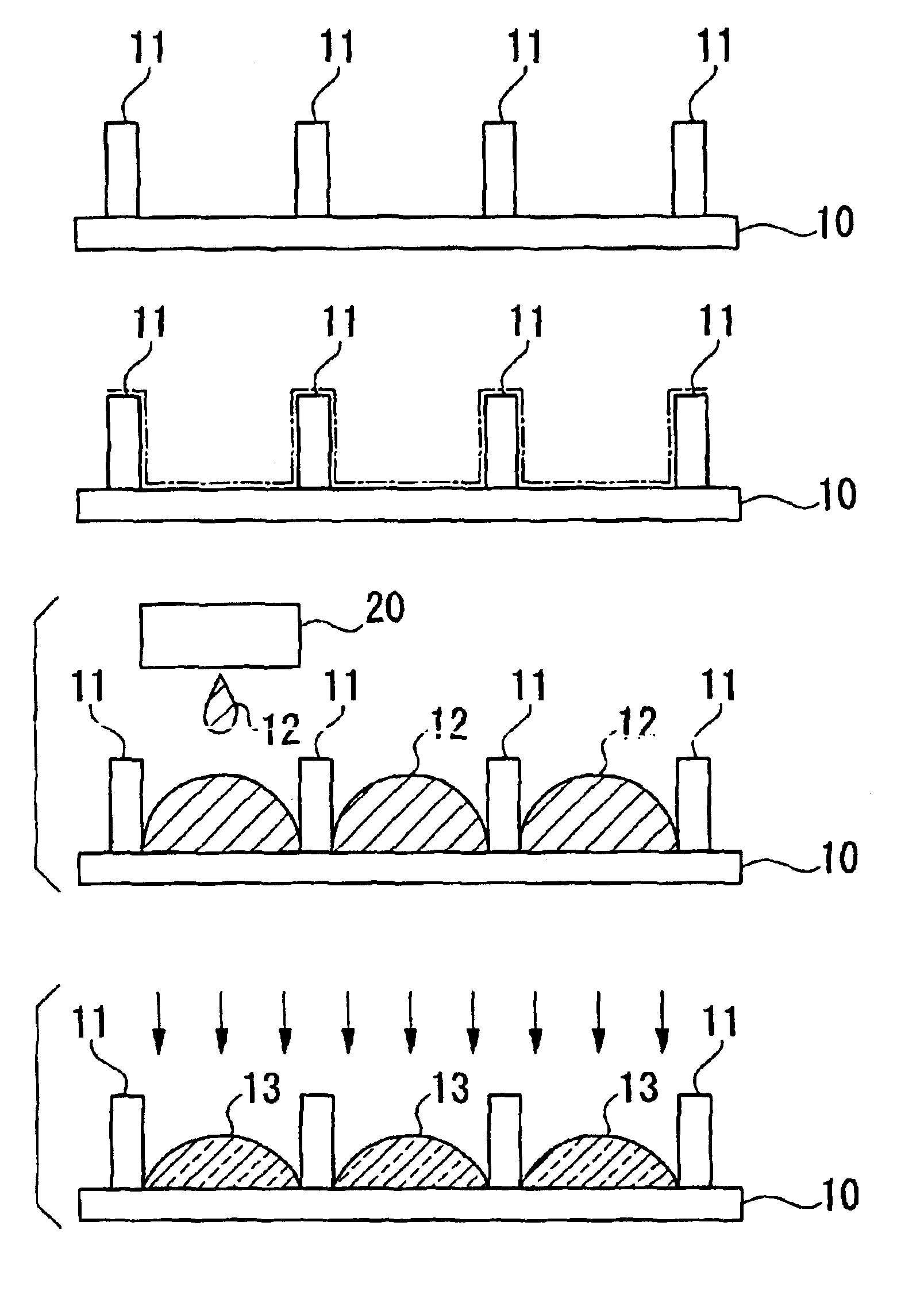
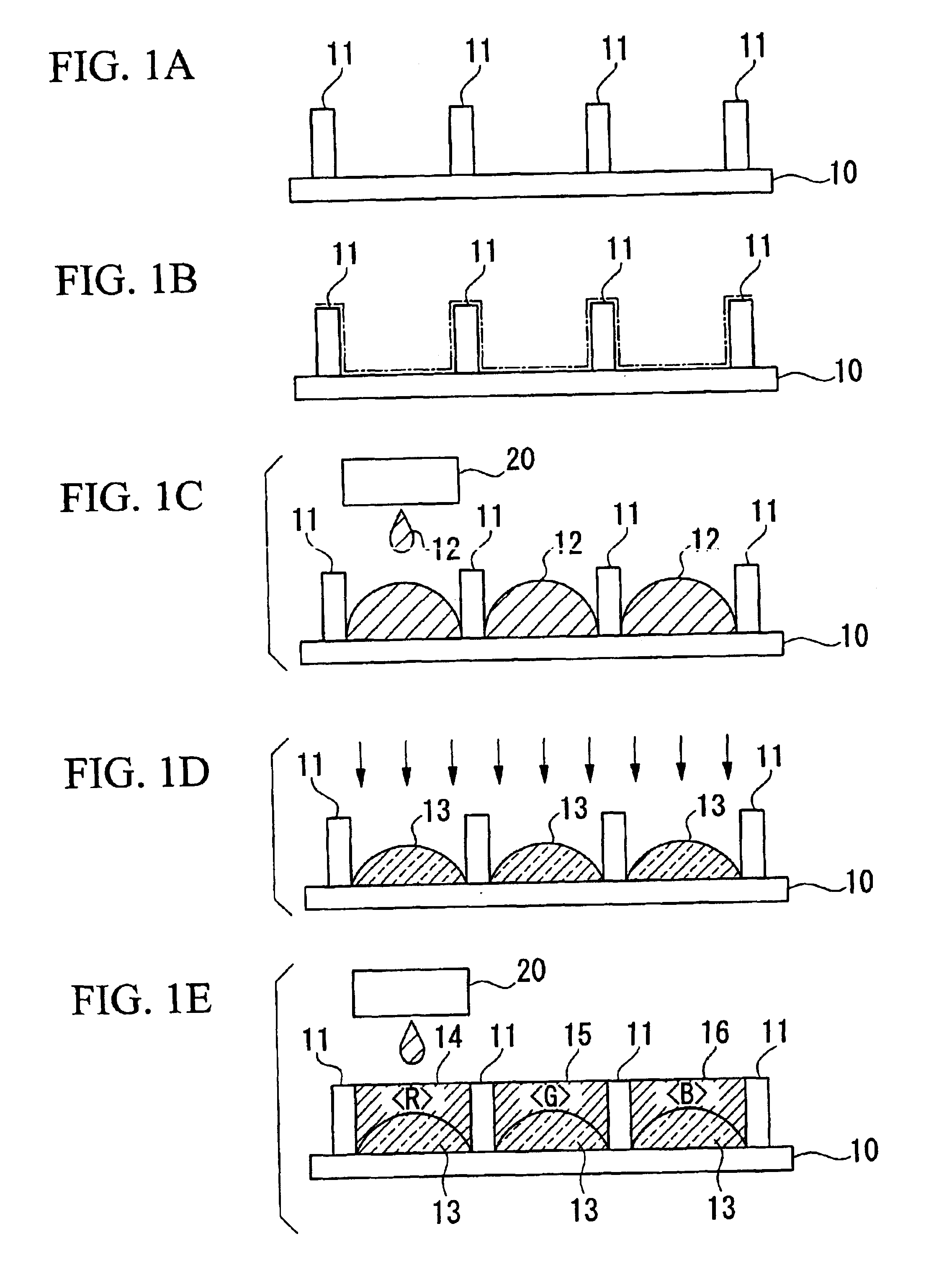
[0046]FIGS. 1A through 1E are figures which show in schematic form a method of manufacture of a color filter, which is an optical device, as a preferred embodiment of the present invention. The color filter which is to be manufactured is to have a structure in which a layer made from a color material and a lens (a micro-lens) are combined together. The method of manufacture of a color filter according to this preferred embodiment includes a bank formation process (FIG. 1A), a lyophobicity enhan...


PUM


Abstract

A method of manufacture of an optical device comprises a process of forming a bank 11 which demarcates a region in which a functional material is distributed, and a process of distributing a lens material 12 in the liquid state in the region which is demarcated by the bank 11, and of thereby forming a lens 13 which is layered against the functional material 14, 15, 16.

Description

BACKGROUND OF THE INVENTION[0001]1. Field of the Invention[0002]The present invention relates to an optical device which includes a layer which is made from a functional material, to a method of manufacture of the same, and to a display device, an electronic device, and a detection device.[0003]Priority is claimed on Japanese Patent Application No. 2002-275912, filed Sep. 20, 2002, and on Japanese Patent Application No. 2003-299196, filed on Aug. 22, 2003, and the contents of which are incorporated herein by reference.[0004]2. Description of Related Art[0005]As an optical device which includes a layer made from a functional material, for example, there is a color filter which incorporates a layer of material of a predetermined color (a colored material layer). In order to enhance the optical performance of such an optical device, it is per se known to utilize a structure in which the layer of optical functional material (the colored material layer and so on) and a lens (a micro lens...

Claims


Application Information

Patent Timeline
IPC IPC(8): B29D11/00G02B5/20G02B3/00G02F1/1335
CPCB29D11/00365G02F1/1335
Inventor KOYAMA, MINORU
Owner SEIKO EPSON CORP
Why Eureka
Try Eureka