Packet switch device and scheduling control method

a packet switch and scheduling control technology, applied in the field of packet switch devices, can solve the problems of large device scale of switching, large quantity of output buffer memories, and inability to perform advanced scheduling of the next cycle, and achieve the effect of reducing processing speed and effective reception of variable-length packets

Inactive Publication Date: 2005-07-19
FUJITSU LTD
View PDF4 Cites 33 Cited by
  • Summary
  • Abstract
  • Description
  • Claims
  • Application Information

AI Technical Summary

Benefits of technology

[0041]In the fourth scheduling control method of the present invention, a similar effect as the eighth packet switch device above can be expected.
[0042]As described above according to the present invention, executing scheduling by the frame in parallel processing not only makes it pos

Problems solved by technology

However, since strictly switching such variable length packets requires the processing of every byte, it is generally necessary to use a high-speed process, in which high-speed switching is difficult.
Therefore, a device having a large scale of switching requires a large quantity of output buffer memories.
However, in order to realize scheduling by the frame, it is prohibited for other output lines to perform scheduling on an input line through which a frame is sent.
Therefore, upon sc

Method used


Image

  • Packet switch device and scheduling control method
  • Packet switch device and scheduling control method
  • Packet switch device and scheduling control method

Examples


Embodiment Construction

[0063]Embodiments of the present invention will be described referring to the drawings.

[0064]Overall Configuration

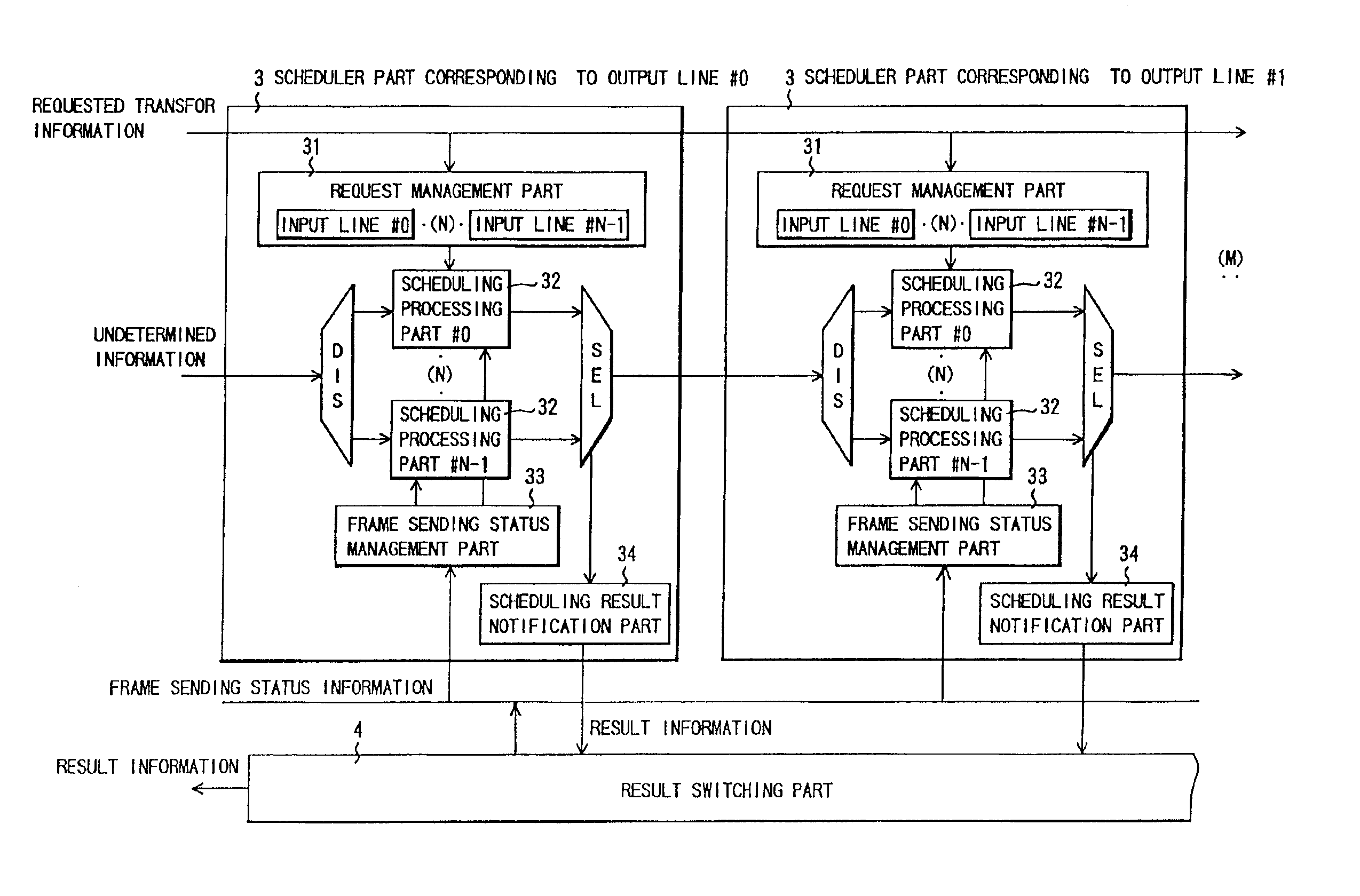
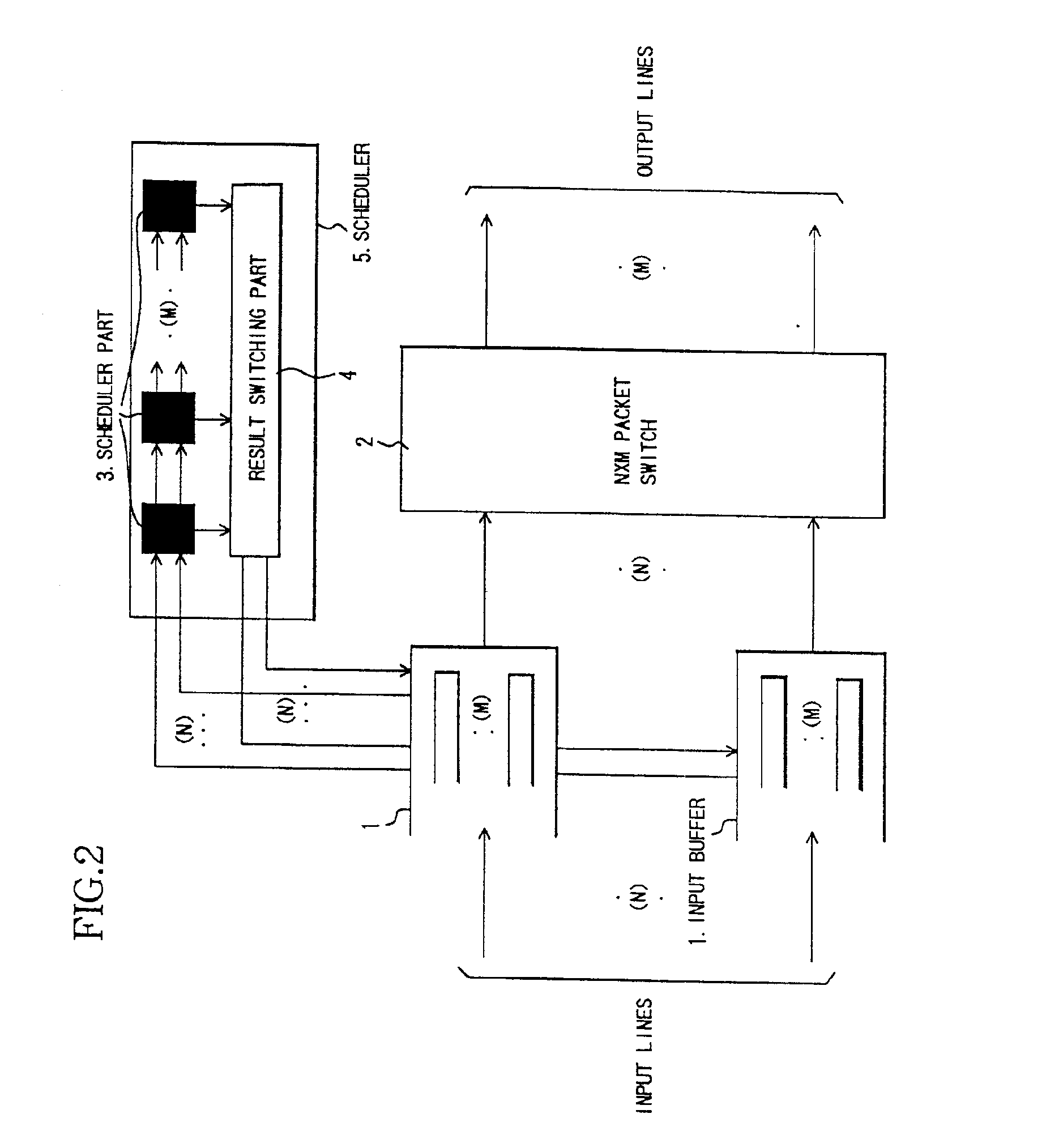
[0065]Referring to FIG. 2 which shows the overall configuration of a packet switch device as one embodiment of the present invention, an input buffer type packet switch device comprises: a plurality of (N) input buffer parts 1, a packet switch of input N×output M matrix (common switch) 2, a plurality of (M) schedulers 3, and a result switching part 4.

[0066]Here, an input buffer part 1 of the N number of input buffer parts 1 are provided to each of the N input interface parts (Input INF in FIG. 5), which correspond to the plurality of (N) input lines (input route). The M scheduler parts 3 and the result switching part 4 constitute the scheduler (scheduling control device) 5. The plurality of (M) output lines (output route) from the packet switch of N×M matrix 2 is received by the output interface part (Output INF in FIG. 5).

[0067]Each input buffer part 1 performs bufferin...


PUM


Abstract

A packet switch device having a plurality of input buffers; a packet switch; a plurality of schedulers, having a pipeline scheduling process module wherein a plurality of time units corresponding to the number of output lines is spent in scheduled sending process of the fixed length packets from the input buffer, and wherein the scheduled sending process is executed in a number of processes, in parallel, the number of processes corresponding to the number of the input lines, having a sending status management module wherein sending status of the fixed length packets which constitute one frame is managed for each of the input lines, and provided corresponding to any of the output lines; and at least one result notification module for notifying the input buffer of result information from the scheduled sending process performed by each of the plurality of schedulers. Further, in the scheduled sending process executed in a number of processes, in parallel, the device does not select the input line sending the fixed length packets corresponding to the same frame, and, after determining a selection, the device maintains the selection of the same input line until the completion of sending the fixed length packets corresponding to the same frame.

Description

BACKGROUND OF THE INVENTION[0001]This invention relates to a packet switch device for transmission of (including exchange, communication, and forwarding, unless specifically limited) fixed length packets, which is applied in a broadband switch, a cross connect switch device, a router device, etc., and more particularly relates to an input buffer type packet switch device as one of the configuration methods of a large scale packet switch device.[0002]In further details, this invention relates, as a packet switch device (an ATM switch device) that performs switching of fixed length packets called cells, to a packet switch device that enables efficient transmission of variable length packets such as IP (Internet Protocol) packets when they are input.[0003]Along with the spread of the Internet in recent years, the IP data traffic (including voice information) in IP communications network systems is increasing at a great rate. In several years it's considered that IP traffic will become ...

Claims


Application Information

Patent Timeline
IPC IPC(8): H04L12/56H04L12/937H04L12/931
CPCH04L49/254H04L49/3063H04L49/608H04L49/205H04L49/30H04L49/503H04L49/508H04L2012/5679
Inventor MATSUOKA, NAOKITOMONAGA, HIROSHIKAWARAI, KENICHI
Owner FUJITSU LTD
Why Eureka
Try Eureka