
Image forming apparatus capable of inhibiting photoreceptor filming and color toner mixing

a technology of image forming apparatus and photoreceptor, which is applied in the direction of electrographic process apparatus, instruments, optics, etc., can solve the problems of color mixing, scratching the surface, and difficult color mixing recognition, and achieve the effect of prolonging the life of the photoreceptor

Inactive Publication Date: 2005-07-19
KK TOSHIBA +1
View PDF13 Cites 21 Cited by
  • Summary
  • Abstract
  • Description
  • Claims
  • Application Information

AI Technical Summary

Benefits of technology

[0016]The present invention has been made to solve the above problems, and an object thereof is to provide an image forming apparatus which is capable of inhibiting filming on a photoreceptor and color toner mixing, while prolonging the life of the photoreceptor.

Problems solved by technology

If no cleaner is available for cleaning the surface of the photoreceptor, the reverse-transferred toner is collected and recovered into the developing device of the downstream image forming station, with the result that color mixing occurs.
Further prior art discloses an arrangement of yellow unit at an upstream image forming station so that it is made difficult to recognize color mixing even if such mixing occurs at a downstream image forming station (Japanese Patent Application KOKAI Publication No.
In addition, in an image forming apparatus of cleanerless type which employs a combination of contact electrification by a magnetic brush using mainly magnetic carrier and two-component development using magnetic carrier and toner in the developing device, there is a problem in that the magnetic carrier is attached to the surface of the photoreceptor thereby to scratch the surface.
This is due to rotation of the photoreceptor having on the surface thereof carrier which is harder and larger in size than toner and stuck to the surface of the photoreceptor having no cleaner, and this problem tends to occur in an apparatus having a transfer device of contact transfer type.
Although the various provisions have been thus proposed for the solution of the problems associated with toner color mixing and scratching of photoreceptor surface by carrier, the cleanerless process has other problems.
On the other hand, however, any hard dirt stuck on the photoreceptor surface cannot be removed.
Repeated image forming operation may allow unwanted residual toner on the photoreceptor to adhere its surface, thereby causing a trouble in image forming operation.
If there is even a slight difference in surface speed between the photoreceptor and the transfer member or if the pressure to be applied during the transferring is too strong, part of toner and of additive substances to the toner are attached gradually to the surface of the photoreceptor and finally stuck hard on the surface to such an extent that they are difficult to be removed.
Although this method can improve the situation to a certain extent, the improvement cannot be said to be enough.
In such structure, however, the surfaces of the photoreceptor and the transfer belt are susceptible to scratches, which hampers the extended serviceable life of the photoreceptor that is one of the advantages of the cleanerless process.

Method used


Image

  • Image forming apparatus capable of inhibiting photoreceptor filming and color toner mixing
  • Image forming apparatus capable of inhibiting photoreceptor filming and color toner mixing
  • Image forming apparatus capable of inhibiting photoreceptor filming and color toner mixing

Examples


first embodiment

(First Embodiment)

[0045]The following will describe in detail a first embodiment of the image forming apparatus of the invention.

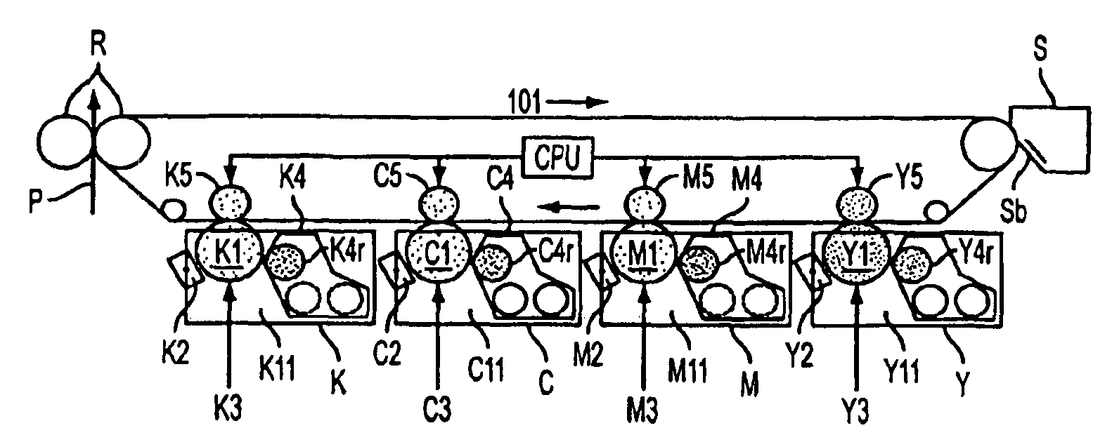
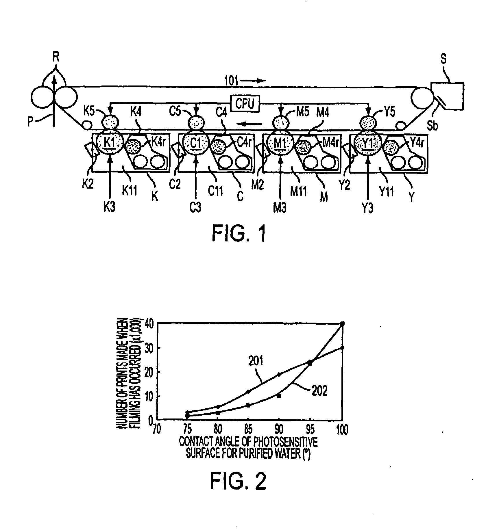
[0046]FIG. 1 shows schematically the peripheral arrangement of image forming stations of the embodiment of image forming apparatus of the present invention. The image forming apparatus in the illustrated embodiment is a so-called tandem type image forming apparatus which makes possible formation of a color image. In this image forming apparatus, yellow image forming station Y, magenta image forming station M, cyan imaging forming station C and black image forming station K are arranged substantially in parallel to the rotating direction of a transfer belt 101 (transfer member) (moving direction of the transfer surface of the transfer belt). Adjacent to the belt surface of the transfer belt 101 is provided a cleaning device S having a cleaning blade Sb for mechanically removing toner particles and paper powder attached on the belt surface.

[0047]Photorecepto...

second embodiment

(Second Embodiment)

[0086]The following will describe in detail a second embodiment of image forming apparatus according to the present invention. This embodiment is a modification of the above-described first embodiment, and its structure as an image forming apparatus is substantially the same as that of the first embodiment. Therefore, those descriptions which have been already made with reference to the first embodiment will be omitted.

[0087]As already mentioned in earlier part hereof, rubbing contact between the photosensitive surface of photoreceptor and the belt surface of transfer belt is one of the causes of filming on photoreceptor.

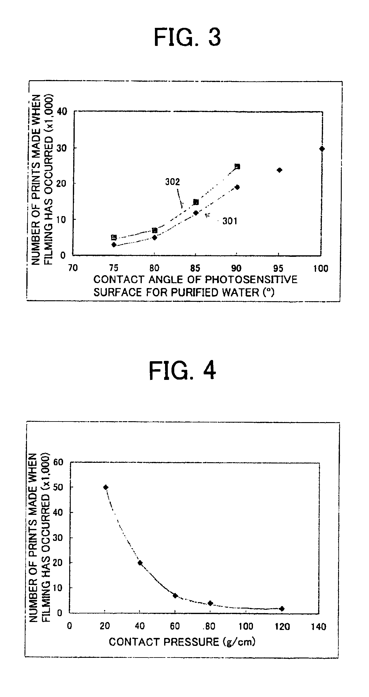
[0088]A major factor in the stress applied to toner is the contact pressure between the photosensitive surface of a photoreceptor and the belt surface of a transfer belt (contact pressure hereinafter). With a decrease in the contact pressure, the stress to the toner or to the photoreceptor is reduced, and hence the tendency of filming on photorece...

third embodiment

(Third Embodiment)

[0099]The following will describe in detail a third embodiment of image forming apparatus according to the present invention. This embodiment is a modification of the above-described respective embodiments, but the structure as an image forming apparatus is substantially the same as that of the above embodiments. Therefore, those descriptions which have been already made with reference to the above-described respective embodiments will be omitted.

[0100]In the so-called tandem type image forming apparatus in which a plurality image forming stations is arranged, a larger quantity of transferred toner will be passed to an image forming station than to an image forming station located upstream thereof. In such a case, if toner of the same type is used for both upstream and downstream image forming stations, filming tends to occur more at the developing device of the downstream image forming station.

[0101]Consequently, by setting the contact pressure lower for the downs...


PUM


Abstract

An image forming apparatus is provided which is capable of inhibiting filing on photoreceptor and color toner mixing, while prolonging the life of the photoreceptor. The image forming apparatus includes a photoreceptor having a photosensitive surface carrying thereon an electrostatic latent image, a developing device for forming a toner image on the photosensitive surface and electrically recovering toner remaining on the photosensitive surface after image forming operation at the photosensitive surface, a transfer belt 101 having a belt surface which is in contact engagement with the photosensitive surface, and a cleaner S for removing toner attached on the belt surface, wherein the contact angle of the photosensitive surface for water is greater than that of the belt surface for water.

Description

BACKGROUND OF THE INVENTION[0001]1. Field of the Invention[0002]The present invention relates to an image forming apparatus.[0003]2. Description of the Related Art[0004]Cleanerless process dispensing with a cleaner such as cleaning blade or the like adjacent to the surface of a photoreceptor is advantageous in terms of the miniaturization of apparatuses and toner savings, and technologies for developing with simultaneous cleaning in reversal development have been heretofore disclosed. Such technologies for developing with simultaneous cleaning can be used effectively for the recent full-color image formation by an image forming apparatus and they are going to be employed in 4-unit tandem type image forming apparatuses.[0005]A tandem type image forming apparatus is so constructed that a toner image transferred to a transfer belt or a sheet at an upstream image forming station is rushed as it is to its downstream image forming station. During this rushing, depending on the conditions,...

Claims


Application Information

Patent Timeline
Patent Type & Authority Patents(United States)
IPC IPC(8): G03G15/00G03G15/08G03G15/30G03G15/01G03G15/16
CPCG03G15/75G03G15/161G03G2215/00957G03G2215/0119
Inventor WATANABE, TAKESHITAKAHASHI, MASASHIAOKI, SHINJI
Owner KK TOSHIBA
Learn More