

Remotely releasable support strut
- Summary
- Abstract
- Description
- Claims
- Application Information
AI Technical Summary
Benefits of technology
Problems solved by technology
Method used
Image

Examples
Embodiment Construction
[0022]The following detailed description of the invention is merely exemplary in nature and is not intended to limit the invention or the application and uses of the invention. Furthermore, there is no intention to be bound by any theory presented in the preceding background of the invention or the following detailed description of the invention.
[0023]While the present invention is described by way of a support structure or strut that is particularly adapted for use in connection with spacecraft deployable systems, those of skill in the art will understand that this is merely for convenience of explanation and not intended to be limiting, and that the present invention is useful and applicable to terrestrial (land and marine) and aircraft based systems as well as space based systems.
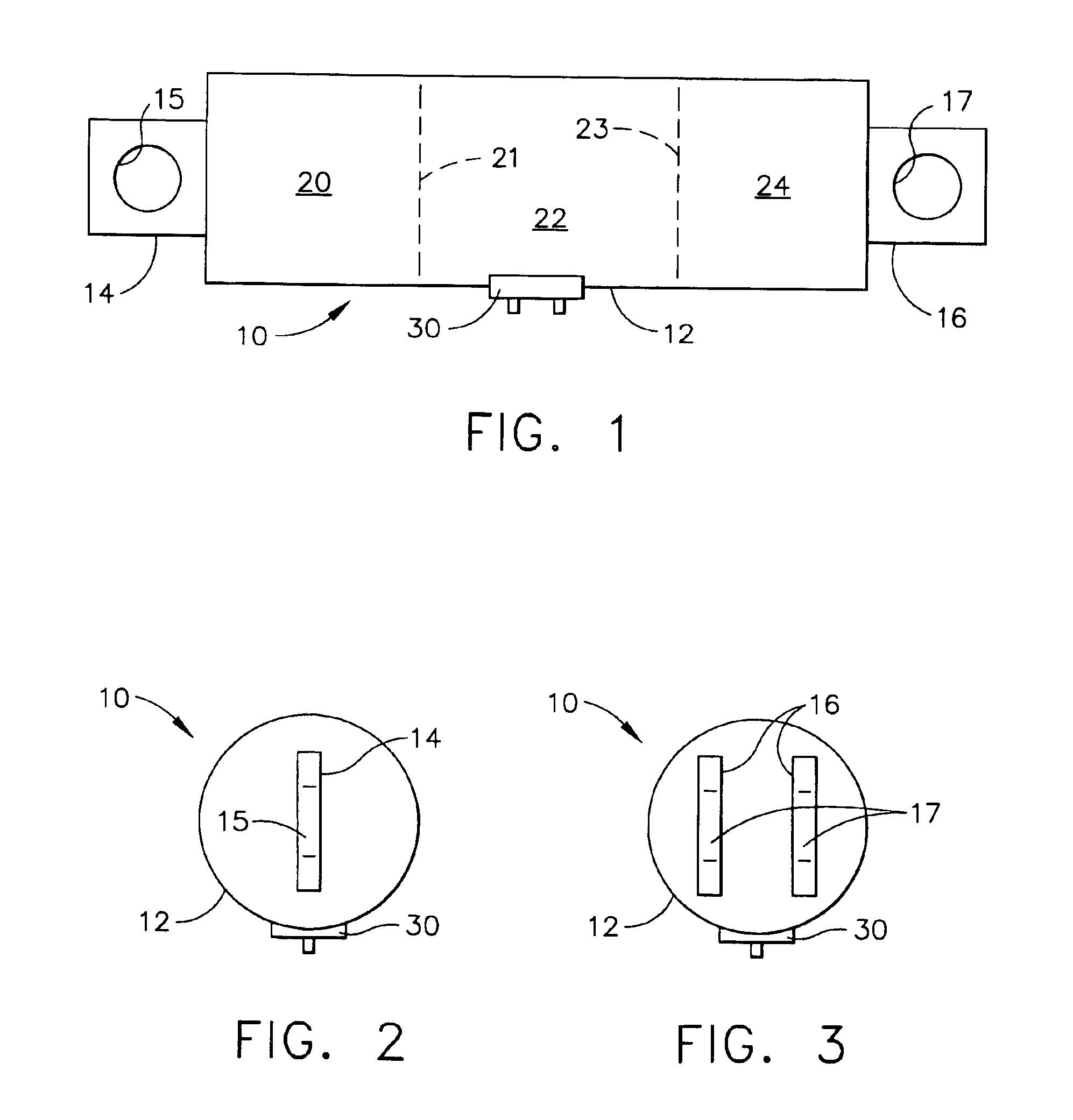
[0024]FIG. 1 is a simplified conceptual side view of remotely releasable support strut 10 according to the present invention. FIG. 2 is a left side end view of the support strut of FIG. 1. FIG. 3 is a ri...
PUM
 Abstract
Description
Claims
Application Information