
Axle weight distribution system

Inactive Publication Date: 2005-07-26
WHEEL MONITOR
View PDF6 Cites 77 Cited by
  • Summary
  • Abstract
  • Description
  • Claims
  • Application Information

AI Technical Summary

Benefits of technology

[0015]Moving an axle group on the trailer or the fifth wheel connection closer or further to / from the tractor can result in the changing of the distribution of the axle weight. Automating the process can result in time saving and improve driver safety.

Problems solved by technology

Overloading a commercial vehicle can create a hazard by reducing the truck's stability and braking ability.
An overloaded commercial vehicle also causes significantly greater wear to public highways and to the vehicle itself.
Moving the suspension slider for the axle group back and forth is not an easy or pleasant task and typically involves following several steps and considerable time.
Sometimes these pins are bound by the weight of the suspension and are difficult to release manually.
This may require the driver to have to rock the trailer to disengage.
Sometimes the judgment of the driver may prove to be incorrect which could result in overweight of one axle group over another.
One of the biggest problems with existing systems is the limitation of the response time of the air suspension systems.
The problem is that there is often a relatively long period of time needed for the air bag to balance itself when the load is changed.

Method used


Image

  • Axle weight distribution system
  • Axle weight distribution system
  • Axle weight distribution system

Examples


Embodiment Construction

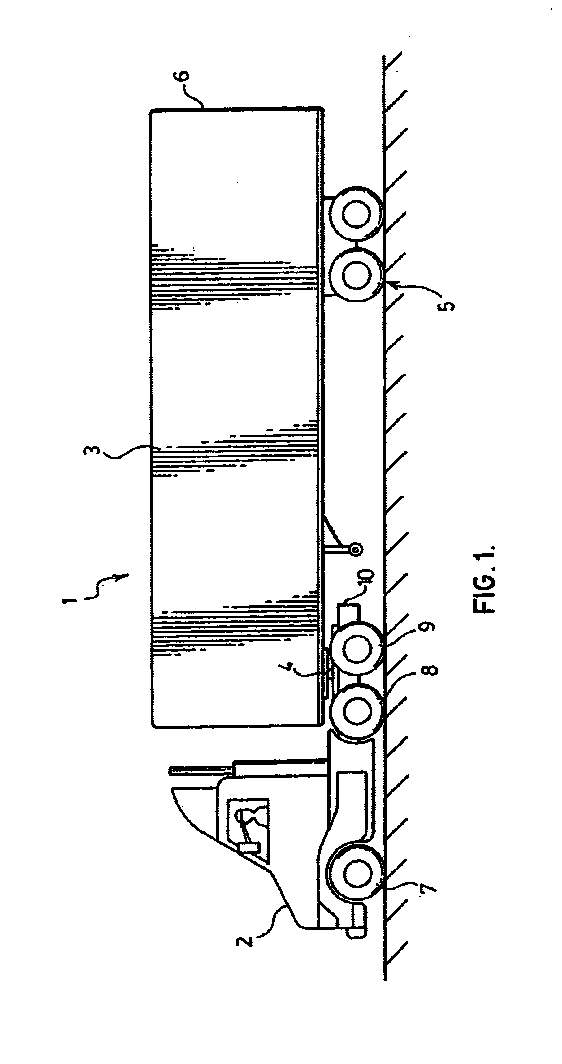
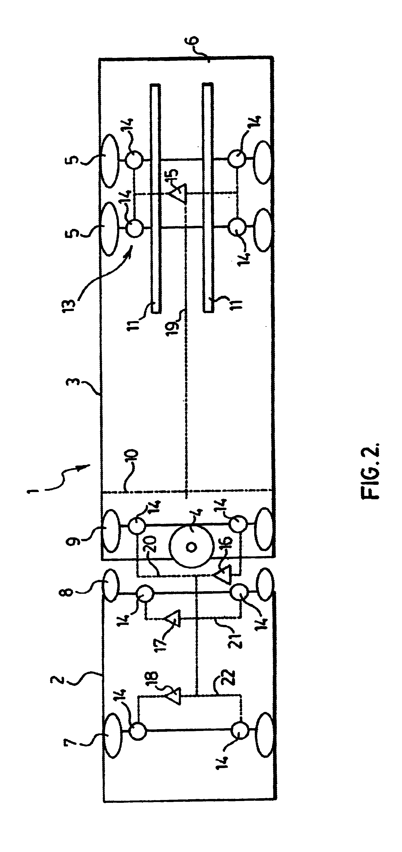
[0026]Referring to FIGS. 1 and 2, a truck and trailer combination of the type on which a system for adjusting weight distribution throughout all axle groups according to the present invention can be installed, is generally indicated at 1. The truck or tractor 2 has a trailer 3 attached to the tractor 2 by a conventional fifth wheel connection 4 or the like. The rear axles 5 on trailer 3 are shown as a tandem axle arrangement. Other arrangements and numbers of axle groups however can be utilized in accordance with the present invention as long as at least one axle group is adjustable forward or back. The rear axles 5 on trailer 3 can be adjusted forward and back relative to the rear 6 of trailer 3. The front and rear axles 7,8,9 of tractor 2 are fixed. However the fifth wheel connection 4 at the rear 10 of truck 2 can also typically be adjusted forward and back.

[0027]By moving the rear axles 5 and / or fifth wheel connection 4 back and forth the cargo weight can be distributed between ...


PUM


Abstract

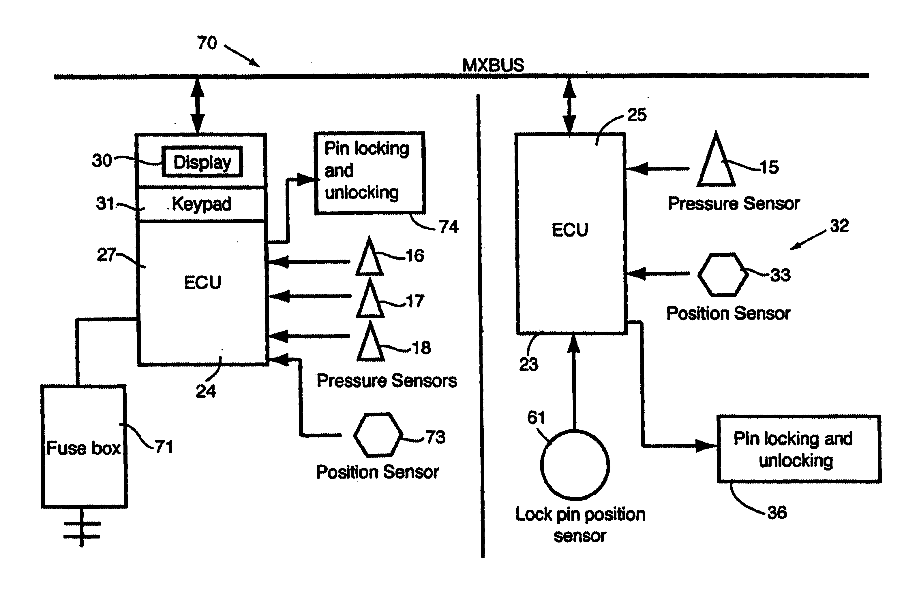
The present invention relates to a system for adjusting weight distribution throughout all axle groups of the truck and trailer. The trailer has at least one axle group mounted on a pair of rails attached to the frame of the trailer. These axle groups are locked in position on the rails by locking pins. The system for adjusting weight distribution according to the present invention measures the weight on every axle group on the truck and trailer. The measurement may be of weight directly by load cells etc. or indirectly, by taking measurements from the air suspension system to calculate weight. The measurements are delivered as an electrical signal to one or more microprocessors capable of receiving the electrical signals and calculating the optimum position of the axle group on the trailer. The position of the trailer axle groups relative to the rails is also determined and the position delivered to the microprocessor(s). The microprocessor(s) is programmed to calculate the weight on each axle group and determine any change in position of the trailer axle group(s) on the rails to optimize the weight distribution. The information is presented to the driver on a display located in the cab of the truck. The system further includes apparatus to lock and unlock the locking pins that lock the trailer axle group(s) in position on the rails. The system also includes a communication interface between the truck and the trailer.

Description

BACKGROUND OF THE INVENTION[0001]1. Field of the Invention[0002]This invention relates to tractor and trailer combinations in heavy trucks. In particular the present invention provides a system for adjusting weight distribution throughout all axle groups of the truck and trailer.[0003]2. Description of the Prior Art[0004]The weight of a vehicle is of crucial importance in the trucking industry. The cost of delivering a load for commercial purposes is often assessed to the customer according to the weight of the load and the distance it must travel. Knowledge of load weight is therefore necessary to ensure that the customer is assessed the full price of transporting the load. Weight information can also be used to optimize the load at or near the vehicle's maximum capacity.[0005]The weight of commercial trucks is also important from the perspective of public safety and highway maintenance. Overloading a commercial vehicle can create a hazard by reducing the truck's stability and brak...

Claims


Application Information

Patent Timeline
IPC IPC(8): B60G17/005
CPCB60G17/005B60G2400/61G01G19/12
Inventor MANTINI, JOHNIANKOULOV, DIMITRE
Owner WHEEL MONITOR
Learn More