Vehicle lamp with indicative mark

a technology of indicative marks and lamps, which is applied in the direction of cycle equipment, lighting and heating apparatus, lighting support devices, etc., can solve the problems of deteriorating the appearance of the lens, glaring light, and increasing manufacturing and controlling costs, so as to achieve cost reduction and minimize the number of parts

Inactive Publication Date: 2005-07-26
KOITO MFG CO LTD
View PDF7 Cites 5 Cited by
  • Summary
  • Abstract
  • Description
  • Claims
  • Application Information

AI Technical Summary

Benefits of technology

[0007]An object of the invention is to provide a vehicle lamp intended to solve the foregoing problems with the formation of an indicative mark on a lens and to prevent the generation of glaring light. Another object of the invention is to provide a vehicle lamp designed to curtail the number of parts and to reduce production cost with a lens for common use when lighting devices having different light distribution characteristics are produced.
[0009]According to the invention, the indicative mark is formed integrally with the dummy portion provided to the reflective mirror and can be visually recognized from the outside of the lighting device through the lens, so that the indicative mark need not be formed on the lens. Thus, the glaring light caused by the indicative mark is not generated. When lighting devices having different light distribution characteristics are produced, moreover, it is only needed to produce reflective mirrors respectively having corresponding indicative marks and the rest of the parts including the lens and the lamp body can be provided for common use, whereby the number of parts is minimized and cost reduction is realizable.

Problems solved by technology

With the application of the insert die for forming the certification mark to the die for forming the lens according to the first technique, a die mark tends to be produced along the periphery of the insert die, thus deteriorating the appearance of the lens.
Moreover, since unevenness is produced on the lens because of the certification mark or the die mark, part of the distribution of light transmitted through the area concerned is abnormally refracted, which results in generating glaring light.
Accordingly, this causes manufacturing and controlling costs to rise.
As the identification mark for identifying the certification mark is needed to be formed on the body side of the lighting device, the man power required for this process rebounds on an increase in production cost.

Method used


Image

  • Vehicle lamp with indicative mark
  • Vehicle lamp with indicative mark
  • Vehicle lamp with indicative mark

Examples


Embodiment Construction

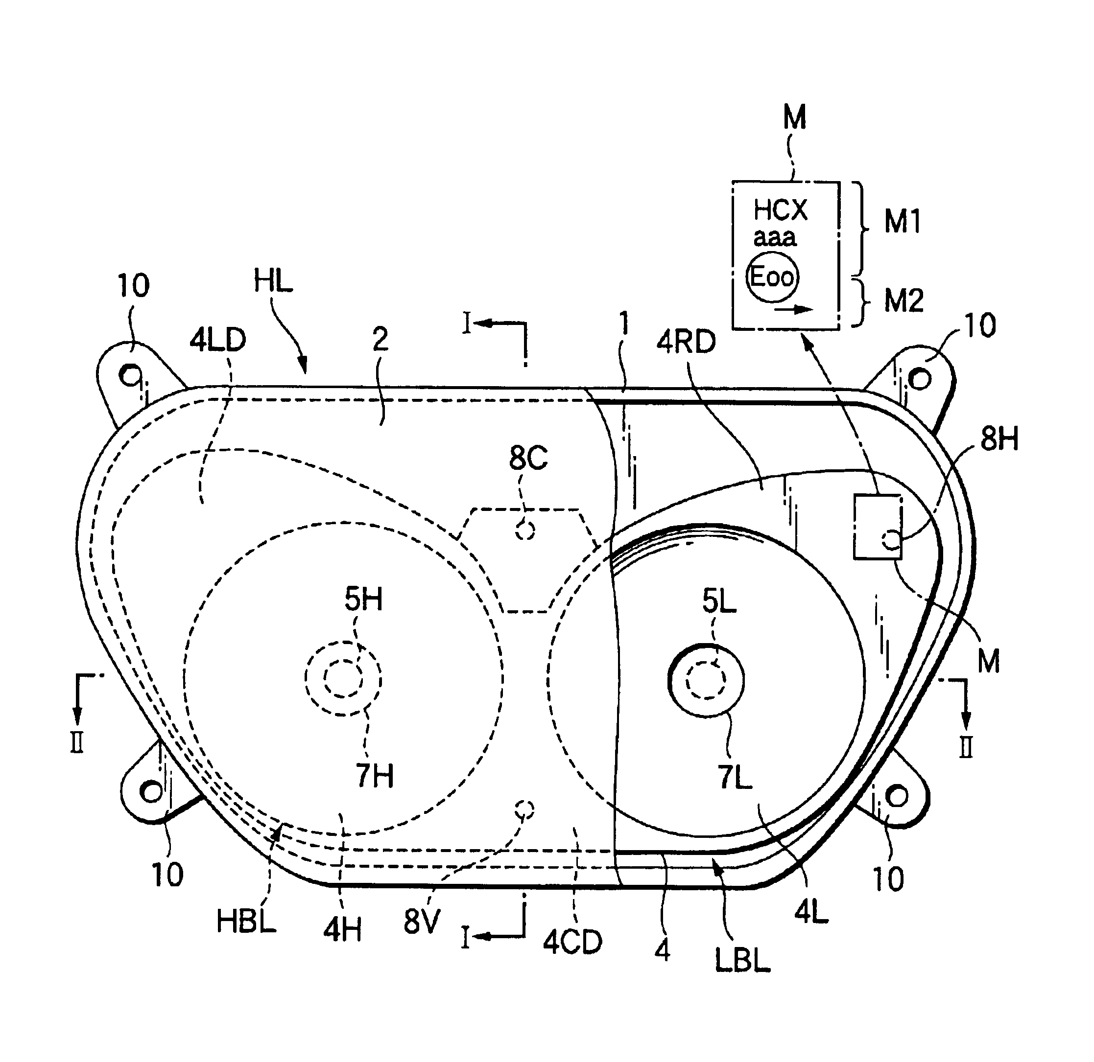
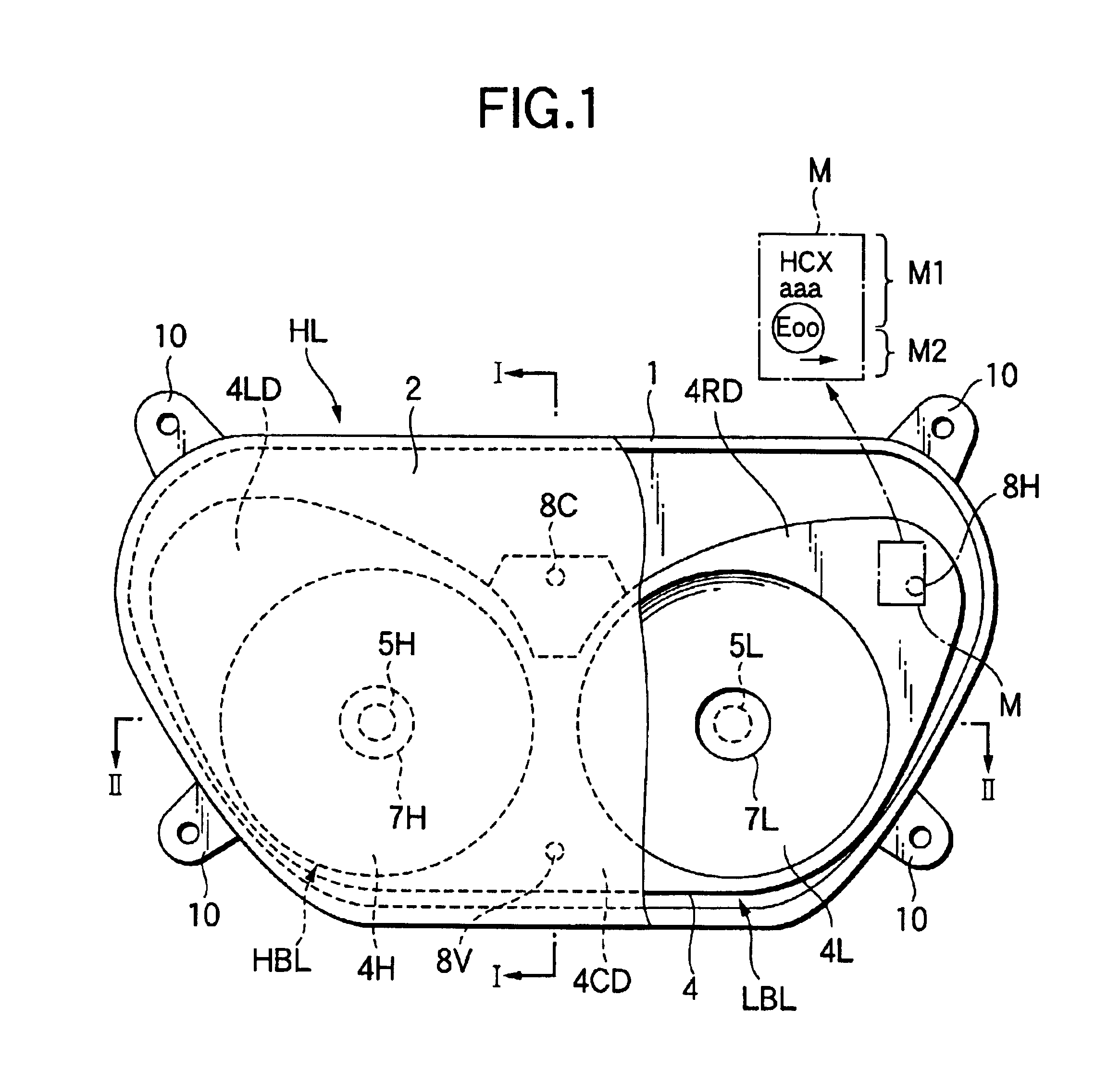
[0016]An embodiment of the invention will now be described by reference to the drawings. FIG. 1 is a fragmentary broken elevational view of the embodiment of the invention applied to a two-lamp type headlamp of a two-wheeled vehicle; FIG. 2, a sectional view taken on line I—I of FIG. 1; FIG. 3, a sectional view taken on line II—II of FIG. 1; and FIG. 4, a schematic perspective view broken into parts. In these drawings, a headlamp HL has a high beam lamp HBL on the left-hand side in the elevational view and a low beam lamp LBL on the right-hand side therein that are horizontally disposed. A lamp chamber 3 is formed with a lamp body 1 mounted in the front portion of the body of a two-wheeled vehicle (not shown) and a lens 2 fitted into the front opening 1a of the lamp body 1, a reflector 4 being installed inside the lamp chamber 3. A bracket 10 is formed integrally with the lamp body 1 at a plurality of places close to the back of the lamp body and these brackets 10 is utilized to fit...


PUM


Abstract

A vehicle lamp including light sources, a reflective mirror for effecting desired light distribution by reflecting light emitted from the light sources and a lens disposed in front of the reflective mirror. In the vehicle lamp, the reflective mirror has a dummy portion which makes no contribution to effecting light distribution and is exposed to the outside through the lens, and an indicative mark for identifying the lighting device is formed integrally with the dummy portion. As the indicative mark can be visually recognized from the outside through the lens, the indicative mark needed not be formed on the lens. When lighting devices having different light distribution characteristics are provided, it is only needed to produce reflective mirrors respectively having corresponding indicative marks and the rest of the parts including the lens and the lamp body can be provided for common use.

Description

BACKGROUND OF THE INVENTION[0001]1. Field of the Invention[0002]The present invention relates to a vehicle lamp and particularly to a vehicle lamp having an indicative mark such as a recognition mark for identifying itself or a certification mark for indicating that it meets the standard required.[0003]2. Description of the Related Art[0004]Vehicle lamps may be required to have indicative marks such as recognition marks for indicating the kinds and models of the lamps involved or certification marks for indicating that the lamps involved have met the standards. For example, headlamps of two-wheeled vehicles are manufactured so that they correspond with the keep-to-the-left traffic in Britain and with the keep-to-the-right traffic in other European countries and they direct the low beams of headlamps leftward (hereinafter called the leftward light distribution) and also rightward (hereinafter called the rightward light distribution), respectively. Consequently, such a headlamp is req...

Claims


Application Information

Patent Timeline
Patent Type & Authority Patents(United States)
IPC IPC(8): B60Q1/06B60Q1/04F21V14/04F21V14/00F21S8/10F21V7/00F21V17/00F21W101/10F21W107/17F21Y101/00
CPCB60Q1/06F21S48/171F21S48/1757F21S41/62F21S41/675B62J6/026
Inventor MOCHIZUKI, SHINICHIKAKIDAIRA, SUSUMU
Owner KOITO MFG CO LTD
Why Eureka
Try Eureka