Medical lead extension and connection system

a technology of electrical connection and medical lead, which is applied in the direction of coupling device connection, coupling device details, therapy, etc., can solve the problems of difficult connection of electrical leads, electrical testing must be performed, and the electrical connection cannot be made at the connector for electrical testing

Inactive Publication Date: 2005-07-26
MEDTRONIC INC
View PDF31 Cites 87 Cited by
  • Summary
  • Abstract
  • Description
  • Claims
  • Application Information

AI Technical Summary

Problems solved by technology

When transvenous leads are implanted with the use of a guide catheter, some difficulties arise pertaining to the leads' electrical connectors.
One difficulty arises when electrical testing must be performed at the time of implant.
If the length of a lead is not sufficiently longer than that of a guiding catheter used to implant the lead, the lead's connector may be covered up by the guide catheter that is pulled back, proximally, to exposed the lead's electrodes; thus, connections cannot be made at the connector for electrical testing.
Another difficulty arises if the lead connector assembly is sized to fit a standard device connector port.
Such connectors generally have a larger diameter than the lead body so that a guiding catheter having a lumen sized for the lead body cannot be removed over these connectors.

Method used


Image

  • Medical lead extension and connection system
  • Medical lead extension and connection system
  • Medical lead extension and connection system

Examples


second embodiment

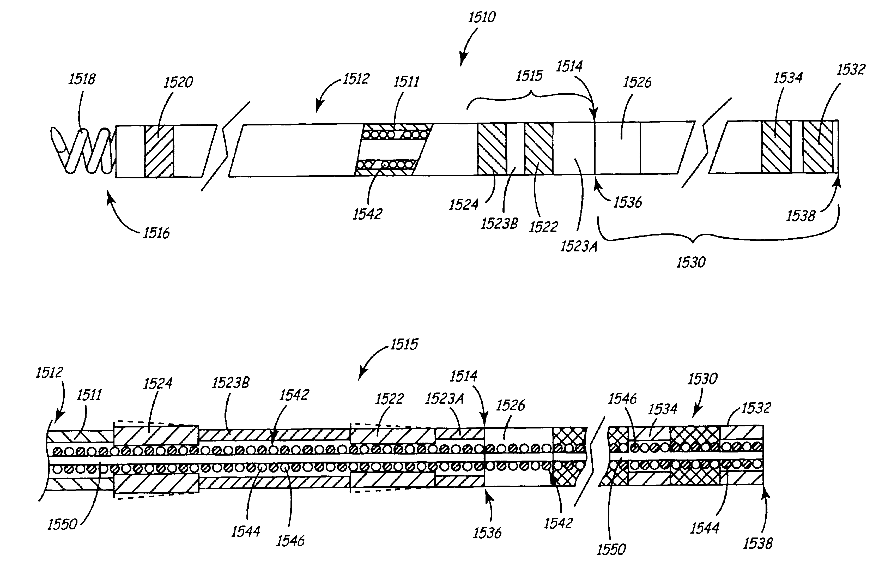
[0082]FIG. 12B is an exploded, side, cut-away view of a proximal portion 1515′ and an extension 1530′ of a lead 1510′. As illustrated in FIG. 12B, filars 1544 and 1546 of conductor coil 1542 are unwound in proximity to proximal end 1514′ of proximal portion 1515′ in order to be routed into a distal end 1536′ of extension 1530′ having a bi-lumen form. As in the embodiment depicted in FIG. 12A, filars 1544 and 1546 are electrically coupled to connector rings 1522 and 1524 and to contact surfaces 1532′ and 1534′ and a severing section 1526′ is positioned in proximity to distal end 1536′ and may be marked in a similar manner described above in conjunction with FIG. 11.

third embodiment

[0083]FIG. 12C is an exploded, side, cut-away view of a proximal portion 1515″ and an extension 1530″, having a bi-lumen form similar to that depicted in FIG. 12B, of a lead 1510″. As illustrated in FIG. 12C, filar 1544 is routed into a first lumen of extension 1530″ and is electrically coupled to both connector ring 1522 and a single contact surface 1532″ of extension 1530″ while filar 1546 is only electrically coupled to connector ring 1524 and is not extended into extension 1530″. In one embodiment according to the present invention, filar 1544 joins connector ring 1522 and contact surface 1532″ to a tip electrode, for example tip electrode 1518 shown in FIG. 11. FIG. 12C further illustrates member 1550 extending from proximal portion 1515″ into one of the lumens of extension 1530″ to provide tensile strength and to limit extensibility. It should be noted that a similar alternate embodiment of proximal portion 1515 and extension 1530 depicted in FIG. 12A may be formed by terminat...


PUM


Abstract

A system for implanting a medical electrical lead includes an elongated lead body and a relatively non-compliant lead extension joined to a proximal end of the proximal portion of the lead body. The lead body includes a plurality of connector rings positioned about a proximal portion of the lead body. The lead extension includes a plurality of temporary contact surfaces and a plurality of conductors wherein each conductor joins a temporary contact surface to a corresponding connector ring.

Description

PRIORITY CLAIM[0001]This application is a continuation-in-part of U.S. patent application Ser. No. 09 / 838,814, filed Apr. 19, 2001, now U.S. Pat. No. 6,705,900 entitled “Lead Up-Sizing Sleeve,” which is incorporated herein by reference in its entirety.FIELD OF THE INVENTION[0002]The present invention relates generally to means for implanting medical electrical leads and, more specifically, to a system for electrically connecting a lead for stimulation therapy.BACKGROUND OF THE INVENTION[0003]Cardiac stimulation devices, including implantable cardiac pacemakers and implantable cardioverter defibrillators (ICDs), are electrically connected to the heart by at least one cardiac lead. Cardiac leads may be introduced transvenously and advanced through a venous pathway to a cardiac implantation site. For example, endocardial leads are commonly used to provide an electrical pathway between a pacemaker or ICD, connected to the proximal end of the lead, and one or more electrodes at the dista...

Claims


Application Information

Patent Timeline
Patent Type & Authority Patents(United States)
IPC IPC(8): A61N1/05A61N1/372A61N1/375H01R24/04H01R24/00H01R31/06H01R13/52H01R24/58
CPCA61N1/056A61N1/3752H01R24/58H01R31/06A61N2001/0578A61N2001/0585H01R13/5224H01R2107/00H01R2201/12
Inventor SOMMER, JOHN L.WILLIAMS, TERRELL M.
Owner MEDTRONIC INC
Why Eureka
Try Eureka