

Apparatus for delivery of fluid to opthalmic surgical handpiece
a technology for opthalmic surgery and apparatus, which is applied in the field of liquefracture technique of cataract surgery, can solve the problems of deteriorating vision, adding unnecessary complexity to the handpiece, and difficult temperature control of heated solutions
- Summary
- Abstract
- Description
- Claims
- Application Information
AI Technical Summary
Benefits of technology
Problems solved by technology
Method used
Image

Examples
first embodiment
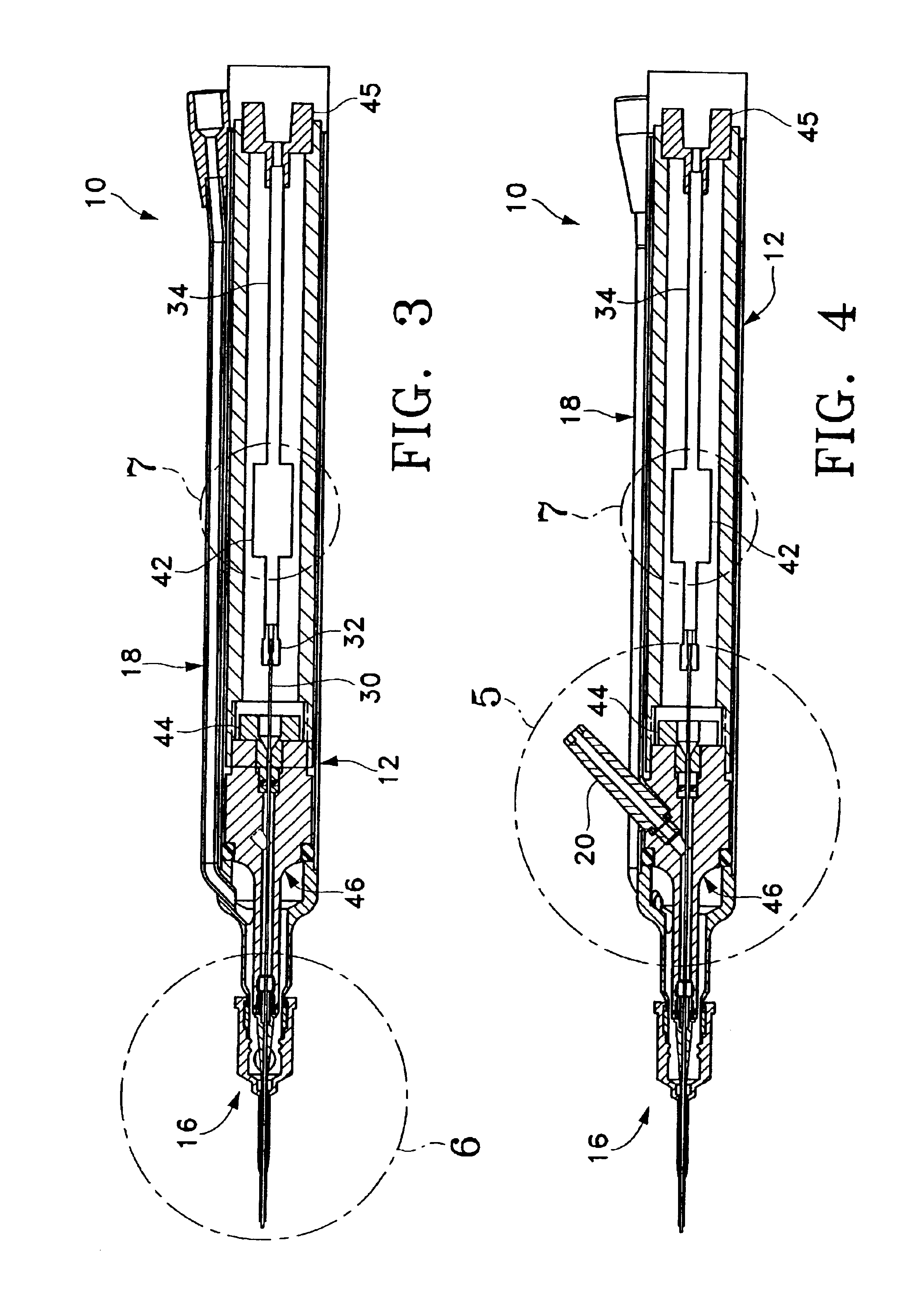
[0038]As best seen in FIG. 7, in the present invention, pumping chamber 42 contains a relatively large pumping reservoir 43 that is sealed on both ends by electrodes 45 and 47. Electrical power is supplied to electrodes 45 and 47 by insulated wires, not shown. In use, surgical fluid (e.g. saline irrigating solution) enters reservoir 43 through port 55, tube 34 and check valve 53, check valves 53 being well-known in the art. Electrical current (preferably Radio Frequency Alternating Current or RFAC) is delivered to and across electrodes 45 and 47 because of the conductive nature of the surgical fluid. As the current flows through the surgical fluid, the surgical fluid boils. As the surgical fluid boils, it expands rapidly out of pumping chamber 42 through port 57 and into tube 30 (check valve 53 prevents the expanding fluid from entering tube 34). The expanding gas bubble pushes the surgical fluid in tube 30 downstream of pumping chamber 42 forward. Subsequent pulses of electrical cu...
second embodiment
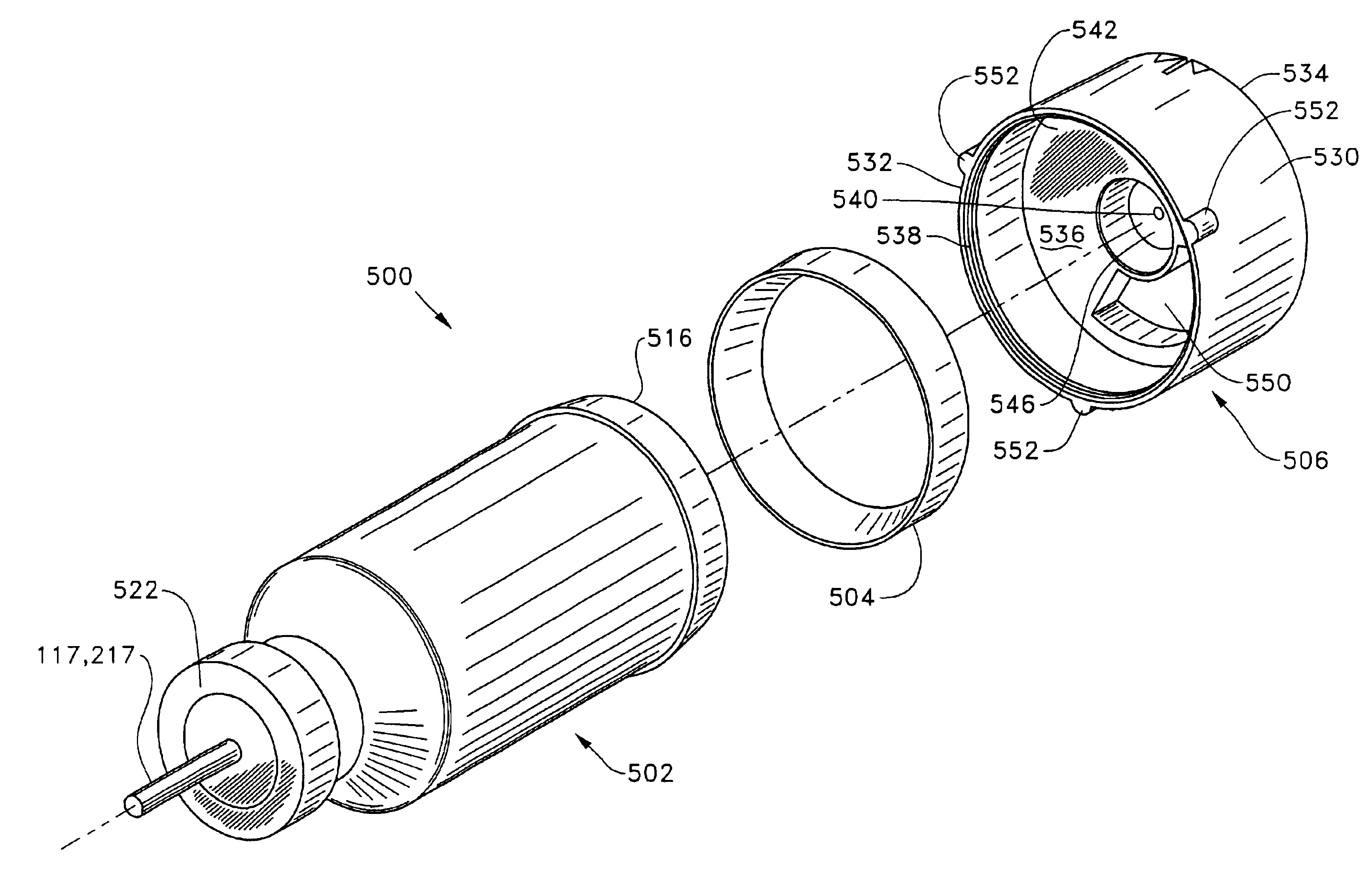
[0039]As best seen in FIGS. 8-10, in the present invention, handpiece 110 generally includes body 112, having power supply cable 113, irrigation / aspiration lines 115, and pumping chamber supply line 117. Distal end 111 of handpiece 110 contains pumping chamber 142 having a reservoir 143 formed between electrodes 145 and 147. Electrodes 145 and 147 are preferably made from aluminum, titanium, carbon or other similarly conductive materials and are electrically insulated from each other and body 112 by anodized layer 159 formed on electrodes 145 and 147. Anodized layer 159 is less conductive than untreated aluminum and thus, acts as an electrical insulator. Electrodes 145 and 147 and electrical terminals 161 and 163 are not anodized and thus, are electrically conductive. Layer 159 may be formed by any suitable anodization technique, well-known in the art, and electrodes 145 and 147 and electrical terminals 161 and 163 may be masked during anodization or machined after anodization to ex...
third embodiment
[0042]As best seen in FIGS. 11-13, in the present invention, handpiece 210 generally includes body 212, having power supply cable 213, irrigation / aspiration lines 215, and pumping chamber supply line 217. Distal end 211 of handpiece 210 contains pumping chamber 242 having a reservoir 243 formed between electrodes 245 and 247. Electrodes 245 and 247 are preferably made from aluminum and electrically insulated from each other and body 212 by anodized layer 259 formed on electrodes 245 and 247. Anodized layer 259 is less conductive than untreated aluminum and thus, acts as an electrical insulator. Electrodes 245 and 247 and electrical terminals 261 and 263 are not anodized and thus, are electrically conductive. Layer 259 may be formed by any suitable anodization technique, well-known in the art, and electrodes 245 and 247 and electrical terminals 261 and 263 may be masked during anodization or machined after anodization to expose bare aluminum. Electrical power is supplied to electrode...
PUM
 Abstract
Description
Claims
Application Information