Controller for permanent magnet motor

a technology of control device and permanent magnet, which is applied in the direction of motor/generator/converter stopper, dynamo-electric converter control, instruments, etc., can solve problems such as synchronous control becoming problemati

Inactive Publication Date: 2005-07-26
TOSHIBA ELEVATOR KK
View PDF13 Cites 9 Cited by
  • Summary
  • Abstract
  • Description
  • Claims
  • Application Information

AI Technical Summary

Benefits of technology

[0009]The present invention has been realized in order to solve the problems described above, and it is a first object of this invention to provide a control device of a permanent magnet electric motor which makes it possible to syn

Problems solved by technology

When the magnetic pole logarithm of the permanent magnet electric motor is not an integral multiple of the number of repeat

Method used


Image

  • Controller for permanent magnet motor
  • Controller for permanent magnet motor
  • Controller for permanent magnet motor

Examples


first embodiment

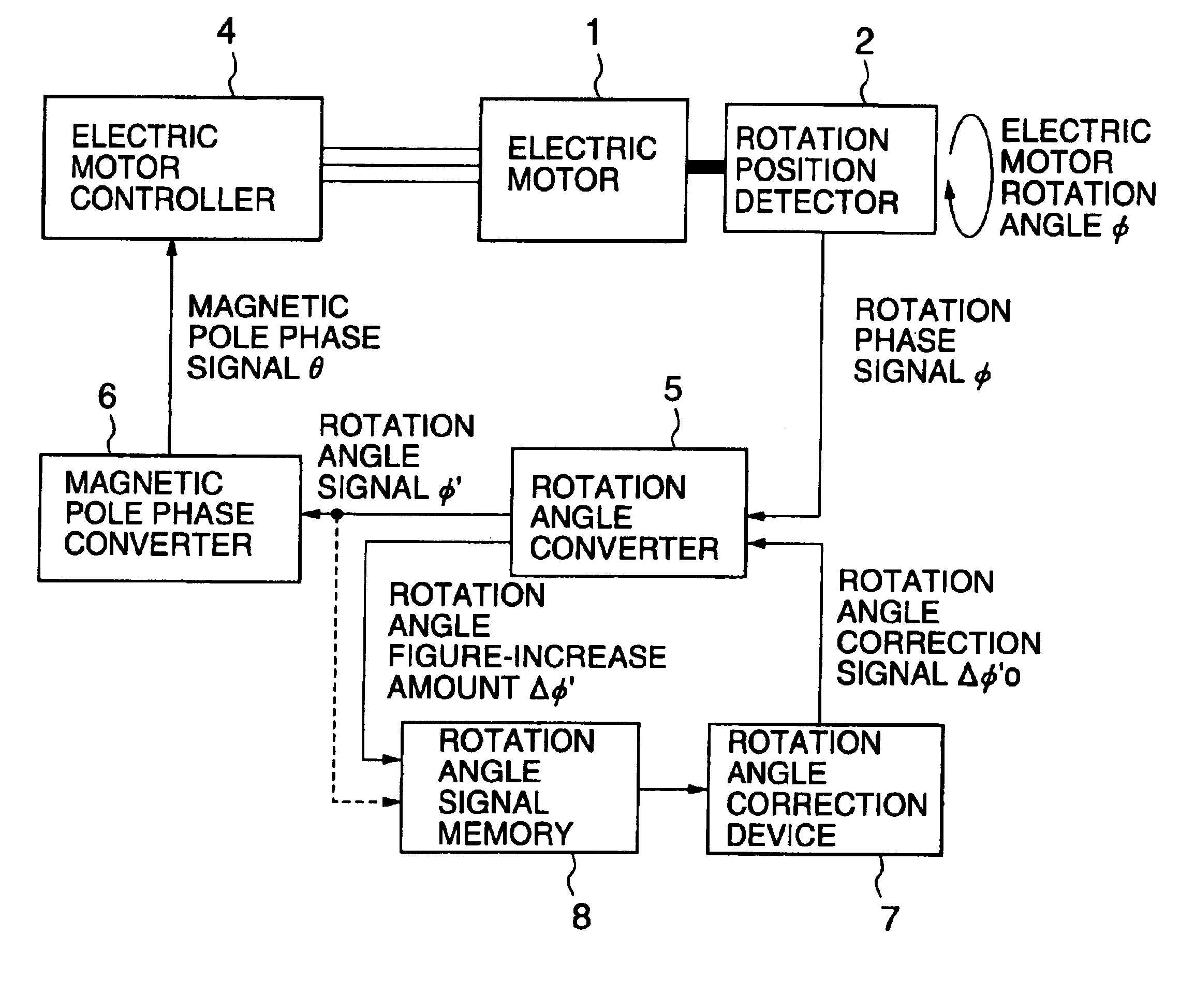
[0041]Subsequently, the operation of the first embodiment will be explained. The rotation position detector 2 outputs a phase signal φ which has a number of repeats n during one rotation of the electric motor 1, that is, a phase signal φ having a number of repeats per number of rotations of the motor of n·Φ. The number of repeats n of the rotation phase signal φ during one rotation of the electric motor 1 is determined according to the signal output format of the rotation position detector 2 itself, and the connection status of the rotating axis and output axis of the electric motor 1, (i.e. whether the rotating axis and the output axis are directly coupled, or whether a pulley for acceleration and deceleration is provided between them, and the like).

[0042]The rotation angle converter 5 converts the rotation phase signal φ to a rotation angle signal φ′ which becomes a phase signal of 360 degrees for one rotation, like the motor rotation angle Φ. Since the relationship between the mo...

second embodiment

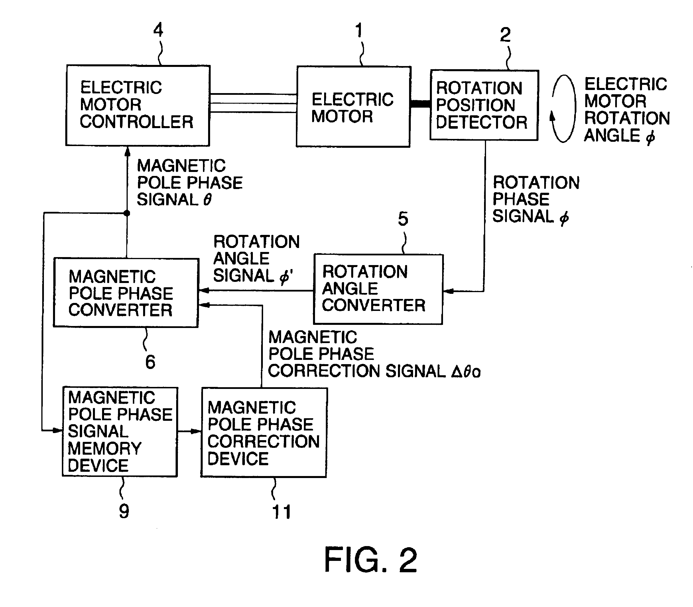
[0048]FIG. 2 is a block line diagram showing the constitution of a control device of a permanent magnet electric motor according to this invention; the same reference codes as those in FIG. 1 represent the same elements, and further explanation of these will be omitted.

[0049]The second embodiment comprises a magnetic pole phase signal memory device 9 being a nonvolatile memory device which, when the power supply to the electric motor controller 4 is cut off, stores the value of the magnetic pole phase signal θ of the magnetic pole phase converter 6 at the time of the power-cut, and saves the stored value until the power is subsequently restored, and a magnetic pole phase correction device 11 which, when the power supply is restored, compared the magnetic pole phase signal stored in the magnetic pole phase signal memory device 9 with the magnetic pole phase signal at the time of power restoration, and determines a correction amount Δθ0 which will make the present magnetic pole phase ...

third embodiment

[0051]FIG. 3 is a block line diagram showing the constitution of a control device of a permanent magnet electric motor according to this invention; the same reference codes as those in FIG. 1 represent the same elements, and further explanation of these will be omitted.

[0052]In the third embodiment, a magnetic pole determination control device 10 is provided instead of the rotation angle signal memory 8 shown in FIG. 1, and the rotation angle correction device 7 corrects the rotation angle signal φ′ output by the rotation angle converter 5 based on the determination result of the magnetic pole determination control device 10.

[0053]When power is restored, the magnetic pole determination control device 10 extracts the output signal of a current detector 14, which detects the current of the electric motor, and, as shown in FIGS. 12A and 12B, measures the response of a step current to the current magnetic pole phase signal θ0, measures the response of a step current to a phase of (θ0+18...


PUM


Abstract

Disclosed is a control device of a permanent magnet electric motor which makes it possible to synchronously control the permanent magnet electric motor even when the magnetic pole logarithm of the permanent magnet electric motor is not an integral multiple of the number of repeats of a rotation phase signal during one rotation.
The control device creates a magnetic pole phase signal based on a rotation phase signal, obtained by detecting the rotation of an output axis of the permanent magnet electric motor, and synchronously controls the permanent magnet electric motor in compliance with the magnetic pole phase signal; the control device comprises a first signal conversion unit which converts the rotation phase signal to a rotation angle signal which is proportional to the rotation angle each time a rotor of the permanent magnet electric motor rotates once, and a second signal conversion unit which converts the rotation angle signal to the magnetic pole phase signal, repeated a number of times equal to a magnetic pole logarithm of the permanent magnet electric motor.

Description

BACKGROUND OF THE INVENTION[0001]1. Field of the Invention[0002]The present invention relates to a control device of a permanent magnet synchronous electric motor (hereinafter referred to simply as “permanent magnet motor”), which creates a magnetic pole phase signal of a rotor based on a rotation phase signal, obtained by detecting the rotation of the output axis of the permanent magnet motor, and synchronously controls the permanent magnet motor in compliance with the magnetic pole phase signal.[0003]2. Description of the Related Art[0004]FIG. 7 is a block diagram showing the constitution of a control device of a permanent magnet motor which drives, for example, an elevator. In FIG. 7, a rotation position detector 2 is connected to an electric motor 1. The rotation position detector 2 detects the rotation position of the electric motor 1, and outputs, for example, a rotation phase signal φh permanent magnet motor having a number of signal repeats of two during one rotation of the ...

Claims


Application Information

Patent Timeline
IPC IPC(8): H02P6/14H02P6/16H02P6/06G01D5/245H02P6/08H02P6/12H02P6/20
CPCH02P6/16H02P6/20
Inventor AKIZUKI, HIROMITSU
Owner TOSHIBA ELEVATOR KK
Why Eureka
Try Eureka