Piston and cylinder assembly

a technology of piston cylinder and piston cylinder, which is applied in the direction of mechanical equipment, vibration dampers, resilient suspensions, etc., can solve the problems of transmission pipes introducing a substantial additional weight, inability to accurately estimate the intended centered stroke position, and the need for circumferential bead, etc., to achieve the effect of reducing the number of parts

Inactive Publication Date: 2001-09-20
STABILUS
View PDF0 Cites 4 Cited by
  • Summary
  • Abstract
  • Description
  • Claims
  • Application Information

AI Technical Summary

Benefits of technology

0012] Accordingly, the number of parts has been reduced compared to the prior art and the use of a tension spring arrangement and a compression spring arrangement allows different restoring forces to be achieved for different piston rod positions.
0013] The compression spring arrangement may be arranged outside the cylinder such that its second end is operatively connected via a switching device supporting the forces of the compression and tension spring arrangements with one of the two principal structural groups. The switching device effects the separation of the effect of the force on the piston-cylinder assembly as a function of the piston rod position, the compression spring arrangement not being active in the area of action of the tension spring arrangement.
0014] To this end, the switching device has a sliding sleeve which is axially movably arranged relative to the two principal groups. The sliding sleeve blocks the effect of the force of one of the two spring arrangements via a stop from a default stroke position of the piston rod.

Problems solved by technology

In this damper, an assembly problem exists in that a circumferential bead is required to be produced as a final step of the method on a transmission pipe as part of the positioning equipment.
The production of the bead introduces a the manufacturing risk that the shape of the transmission pipe will be adversely influenced here which may cause functional problems of the piston-cylinder assembly.
In addition, inaccuracies regarding the intended centered stroke position may be expected.
A further disadvantage of this damper in comparison with a conventional damper is that the transmission pipe introduces a substantial additional weight.
Such a long and rigid pipe is necessarily heavy.
If the production tolerances selected are too wide, jamming forces or skewed positions of the transmission pipe may arise.
However, very narrow tolerances seriously increase costs.

Method used


Image

  • Piston and cylinder assembly

Examples


Embodiment Construction

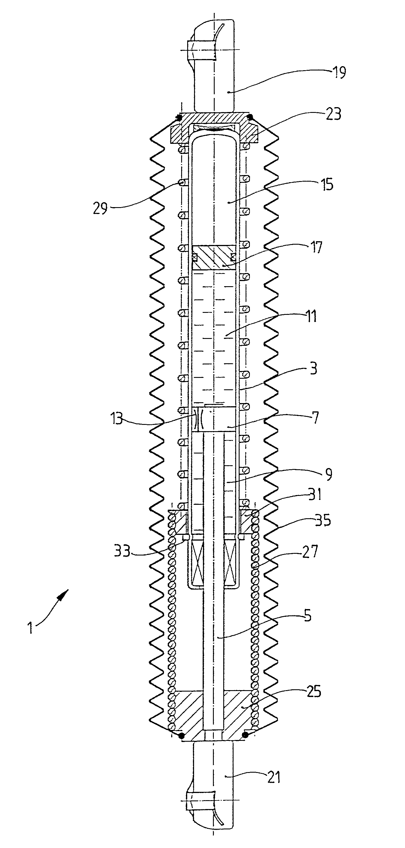
[0022] The FIGURE shows a piston-cylinder assembly 1 according to an embodiment of the present invention. A piston rod 5 is axially movably arranged within a cylinder 3. The piston rod 5 and the cylinder 3 form first and second principal structural groups of the piston-cylinder assembly 1. A piston 7 is fixed to the end of the piston rod 5 arranged in the cylinder 3 and divides the cylinder 3 into two working spaces 9, 11 that are filled with a hydraulic damping medium. The piston 7 has a throttle device 13 which allows the passage of damping medium between the two working spaces 9, 11. The cylinder 3 additionally includes a compensation space 15 which is separated in a fluid-tight manner from the working space 11 by an axially movable separating piston 17. The compensation space 15 is filled with a pressurized gas, or alternatively with a helical compression spring, so that the hydraulic damping medium in the working spaces 9, 11 is under an operating pressure. The compensation spa...


PUM


Abstract

A piston-cylinder assembly has a principal structural group including a cylinder and another principal structural group including a piston rod which has a part-length axially displaceably arranged within the cylinder. The piston rod adopts a default stroke position without external displacement forces acting on the piston-cylinder assembly, the default position being determined by positioning equipment. The positioning equipment includes at least one energy accumulator which acts in the inward and outward movement directions of the piston rod as a function of the stroke position of the piston rod. The at least one energy accumulator includes a tension spring arrangement and a compression spring arrangement. Each of the tension spring arrangement and the compression spring arrangement has a first end which acts in a stationary manner on one of the first and second principal groups and a second end which acts on the other of the first and second principal groups at least with the piston rod outside the default stroke position.

Description

[0001] 1. Field of the Invention[0002] The invention relates to a piston-cylinder assembly including a cylinder and a piston rod which is axially displaceably arranged in the cylinder, the piston rod adopting a stroke position determined by positioning equipment when no external forces are acting on the piston-cylinder assembly.[0003] 2. Description of the Related Art[0004] There are applications in which a piston-cylinder assembly is required to adopt a particular stroke position without external force. An example of such an application is when the piston-cylinder assembly is connected to a switching lever which adopts a central switching position and is moved to a switching point by an actuating force in a first direction. When the actuating force is removed, the piston-cylinder assembly is to resume the central switching position. In the event of an opposed actuating force in a second direction, the piston-cylinder assembly is also required to resume the original central switchin...

Claims


Application Information

Patent Timeline
Patent Type & Authority Applications(United States)
IPC IPC(8): F16F9/19F16F13/00
CPCF16F9/19F16F13/00
Inventor STUMM, ROLFMINTGEN, ROLF
Owner STABILUS
Why Eureka
Try Eureka