Electronic timepiece

a technology of electronic timepieces and timepieces, applied in the field of electronic timepieces, can solve the problem that the second battery cannot be restored normally, and achieve the effect of restoring the electronic timepiece reliably

Active Publication Date: 2015-05-19
SEIKO INSTR INC
View PDF14 Cites 4 Cited by
  • Summary
  • Abstract
  • Description
  • Claims
  • Application Information

AI Technical Summary

Benefits of technology

[0007]It is an aspect of the present application to provide an electronic timepiece capable of restoring a secondary battery in an uncharged state or a low charged state to a normal charged state smoothly and reliably restoring the electronic timepiece from an action stopped state to a normally operating state even in a case where a generated current from a solar panel is not sufficient as a case where the electronic timepiece is under a fluorescent lighting conditions.
[0013]Accordingly, the present invention provides an electronic timepiece which is capable of restoring a secondary battery in an uncharged state or a low charged state to a normal charged state smoothly and reliably restoring the electronic timepiece from an operation stopped state to a normally operating state even though a generated current from the solar panel is insufficient is provided.

Problems solved by technology

. . ” are repeated and hence the secondary battery cannot be restored normally and hence cannot be charged.

Method used


Image

  • Electronic timepiece
  • Electronic timepiece
  • Electronic timepiece

Examples


first embodiment

[0021

Overview of Electronic Timepiece

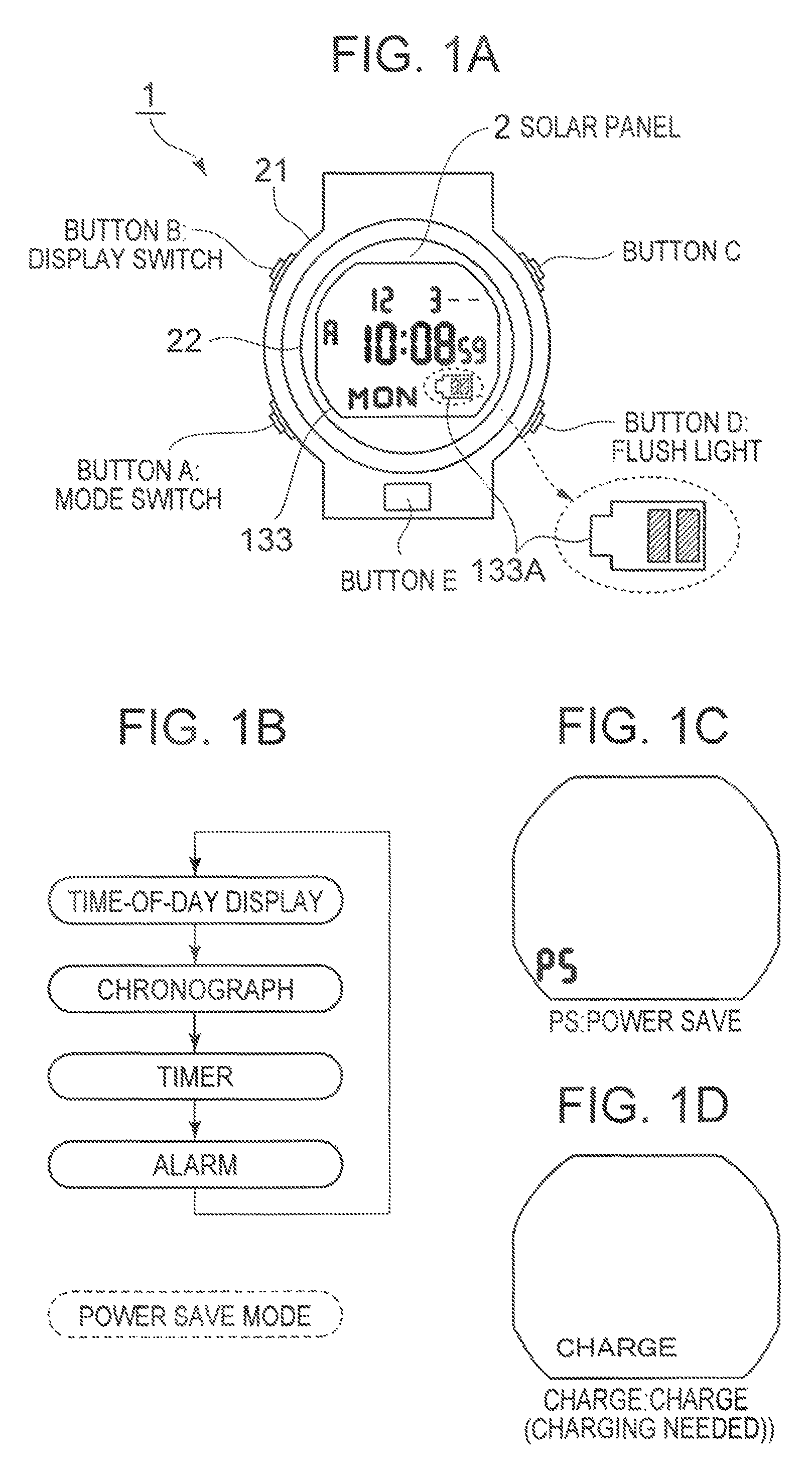
[0022]FIG. 1 is a drawing illustrating an overview of an electronic timepiece according to a first embodiment of the invention.

[0023]As illustrated in FIG. 1, an electronic timepiece 1 of the embodiment includes a body case 21, and an LCD (liquid crystal display) 133 and a solar panel 2 under a transparent plate 22 such as a rectangular-shaped windshield glass or the like chamfered at four corners on a front side of the body case 21. The LCD 133 is provided at a center of the transparent plate 22. The solar panel 2 is arranged in a periphery of the transparent plate 22 so as to surround the LCD 133 in plan view.

[0024]An operating button A, an operating button B, an operating button C, and an operating button D which may be operated by a user are provided on a side surface of the body case 21. An operating button E is provided on a front surface of the body case 21.

[0025]The operating button A outputs a mode change signal, which is a signal for ch...

second embodiment

[0115

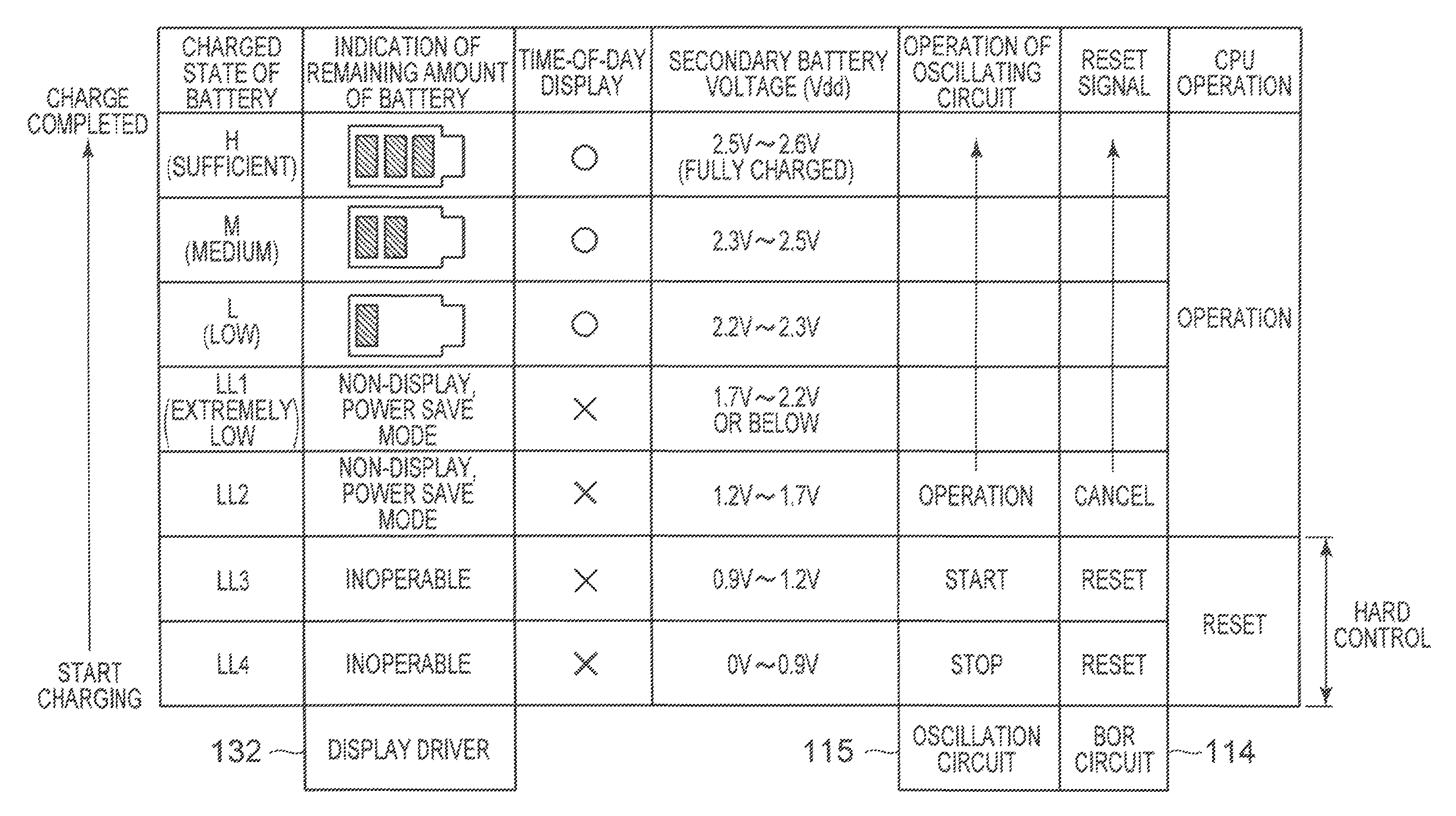
[0116]The electronic timepiece 1 of the first embodiment described above is configured to wait until the secondary battery voltage Vdd is restored to 2.2 V after having started the charging to the secondary battery 3 in the uncharged state, and then perform the time-of-day display.

[0117]In other words, in the electronic timepiece 1 of the first embodiment, the state in which nothing is displayed on the LCD 133 continues for a long time until the secondary battery voltage Vdd reaches 2.2 V after having started the charging to the secondary battery 3. Therefore, the user of the electronic timepiece 1 may misunderstand that the electronic timepiece 1 is broken because nothing is displayed on the LDC for a long time even though the charging is started.

[0118]Therefore, in the second embodiment of the invention, an example in which the charge sign (for example, the charge sign “CHARGE”) is displayed when the charged voltage Vdd of the secondary battery 3 is between 1.7 V and 2.2 V wi...


PUM


Abstract

An electronic timepiece is operated with a power-supply voltage from a secondary battery charged with a voltage from a solar panel. An oscillation circuit generates and supplies a clock signal to a CPU when the voltage charged to the battery is lower than a first voltage. A reset circuit resets the CPU when the voltage charged to the battery does not exceed a second voltage higher than the first voltage, and cancels the reset of the CPU when the voltage charged to the second battery exceeds the second voltage. The CPU starts an operation when the voltage charged to the secondary battery exceeds the second voltage and the reset is cancelled, and performs a time-of-day display on a display unit when the voltage charged to the secondary battery is equal to or higher than a third voltage higher than the second voltage.

Description

BACKGROUND OF THE INVENTION[0001]1. Technical Field[0002]The present invention relates to an electronic timepiece provided with a solar panel.[0003]2. Description of Related Art[0004]Electronic equipment such as an electronic clock is disclosed in the related art (for example, see JP-A-2002-186186). The electronic equipment described in JP-A-2002-186186 is configured to prohibit display when a power voltage is lowered and reaches a first voltage, perform an initializing process when the power voltage reaches a second voltage lower than the first voltage, and then restart the display when the voltage is restored and reaches a third voltage (>first voltage).[0005]Electronic equipment with a power generating apparatus is also disclosed in the related art (for example, see Japanese Patent No.3738334). The electronic equipment described in Japanese Patent No.3738334 is provided with an all clear circuit configured to start an output of an all clear signal to an LSI when the power volt...

Claims


Application Information

Patent Timeline
Patent Type & Authority Patents(United States)
IPC IPC(8): G04G19/06
CPCG04G19/06G04B99/00
Inventor KATO, KAZUOTAKAKURA, AKIRAIHASHI, TOMOHIROHASEGAWA, TAKANORIFUKUSHIMA, TOSHITAKA
Owner SEIKO INSTR INC
Why Eureka
Try Eureka