Impulse radar antenna array and method

a radar and antenna array technology, applied in the direction of individual energised antenna arrays, instruments, and reradiation, etc., can solve the problems of hampered efforts to resolve the situation, no means at the scene, and often faced by law enforcement agencies with hostage situations

Inactive Publication Date: 2005-07-26
HUMATICS CORP
View PDF5 Cites 113 Cited by
  • Summary
  • Abstract
  • Description
  • Claims
  • Application Information

AI Technical Summary

Problems solved by technology

Law enforcement agencies often are confronted with hostage situations where armed intruders are barricaded inside a building.
Officers on the scene generally have no means for determining the number and position of persons within the building, and are thus hampered in their efforts to resolve the situation.
However, without an array of directional devices, it is impossible to determine the location of the targets generating the sound.
Furthermore, moving targets may not make enough sound to be detected.
The drawbacks of this solution are that it takes time to find a crack or drill a hole and it is noisy to do so.
Thus, in a hostage or raid si...

Method used


Image

  • Impulse radar antenna array and method
  • Impulse radar antenna array and method
  • Impulse radar antenna array and method

Examples


Embodiment Construction

[0047]The present invention will now be described more fully in detail with reference to the accompanying drawings, in which the preferred embodiments of the invention are shown. This invention should not, however, be construed as limited to the embodiments set forth herein; rather, they are provided so that this disclosure will be thorough and complete and will fully convey the scope of the invention to those skilled in art. Like numbers refer to like elements throughout.

1. Ultra Wideband / Impulse Radars

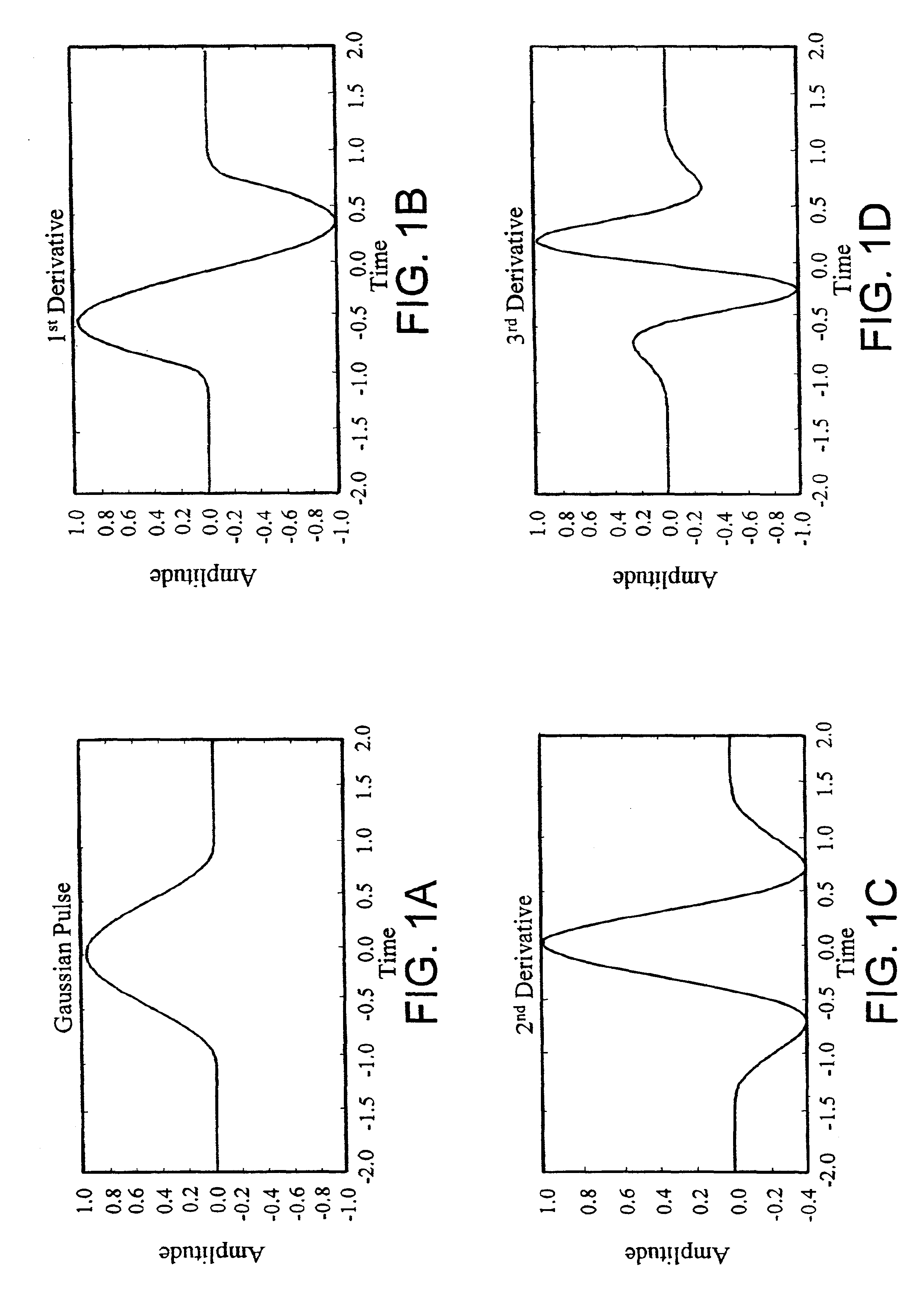
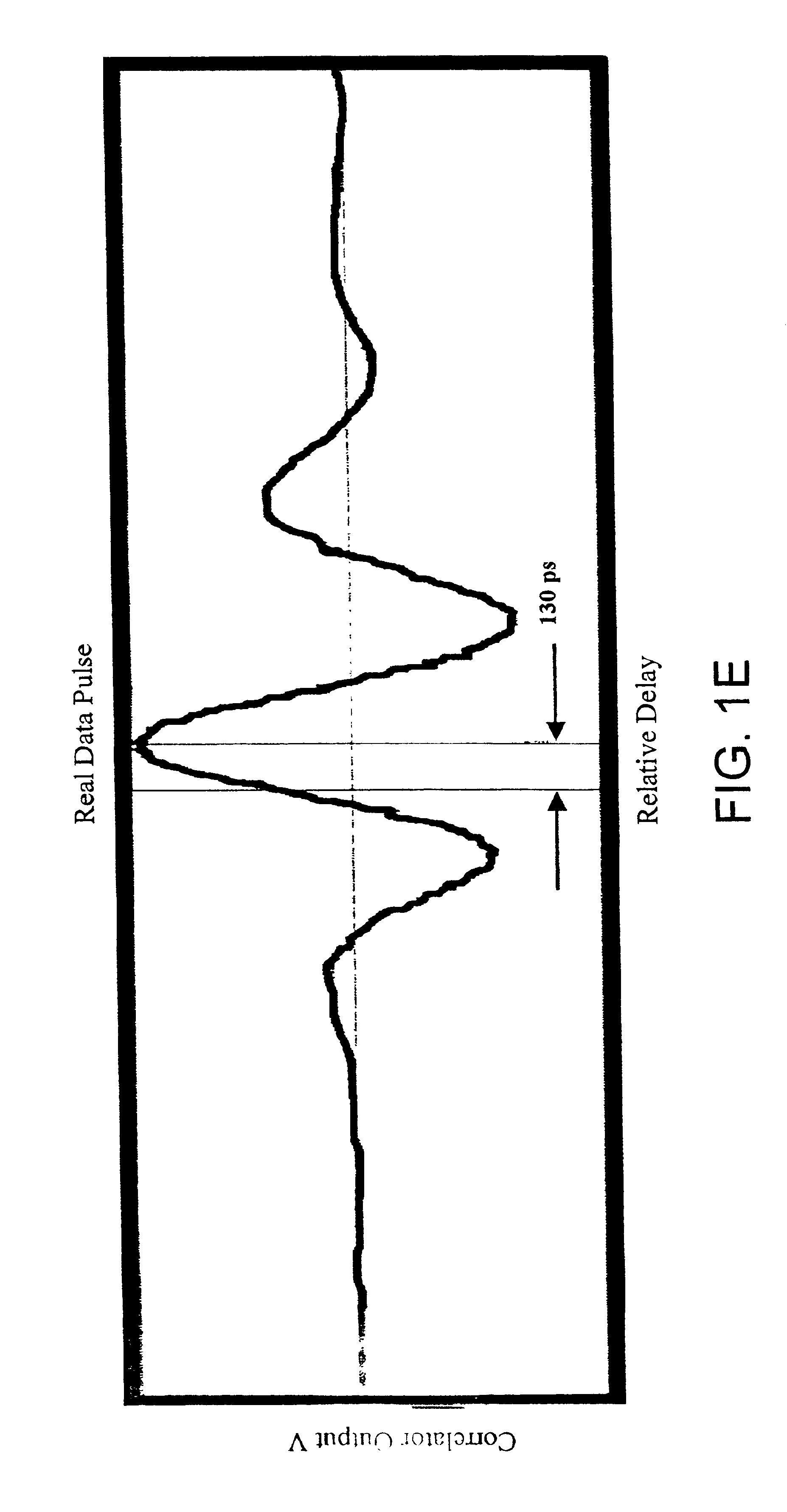
[0048]Recent advances in radio frequency technology have enabled ultra wideband technology (UWB) or impulse radio systems .To better understand the benefits of impulse radio to the present invention, the following review of impulse radio follows. Impulse radio has been described in a series of patents, including U.S. Pat. No. 4,641,317 (issued Feb. 3, 1987), U.S. Pat. No. 4,813,057 (issued Mar. 14, 1989), U.S. Pat. No. 4,979,186 (issued Dec. 18, 1990) and U.S. Pat. No. 5,363,108 (iss...


PUM


Abstract

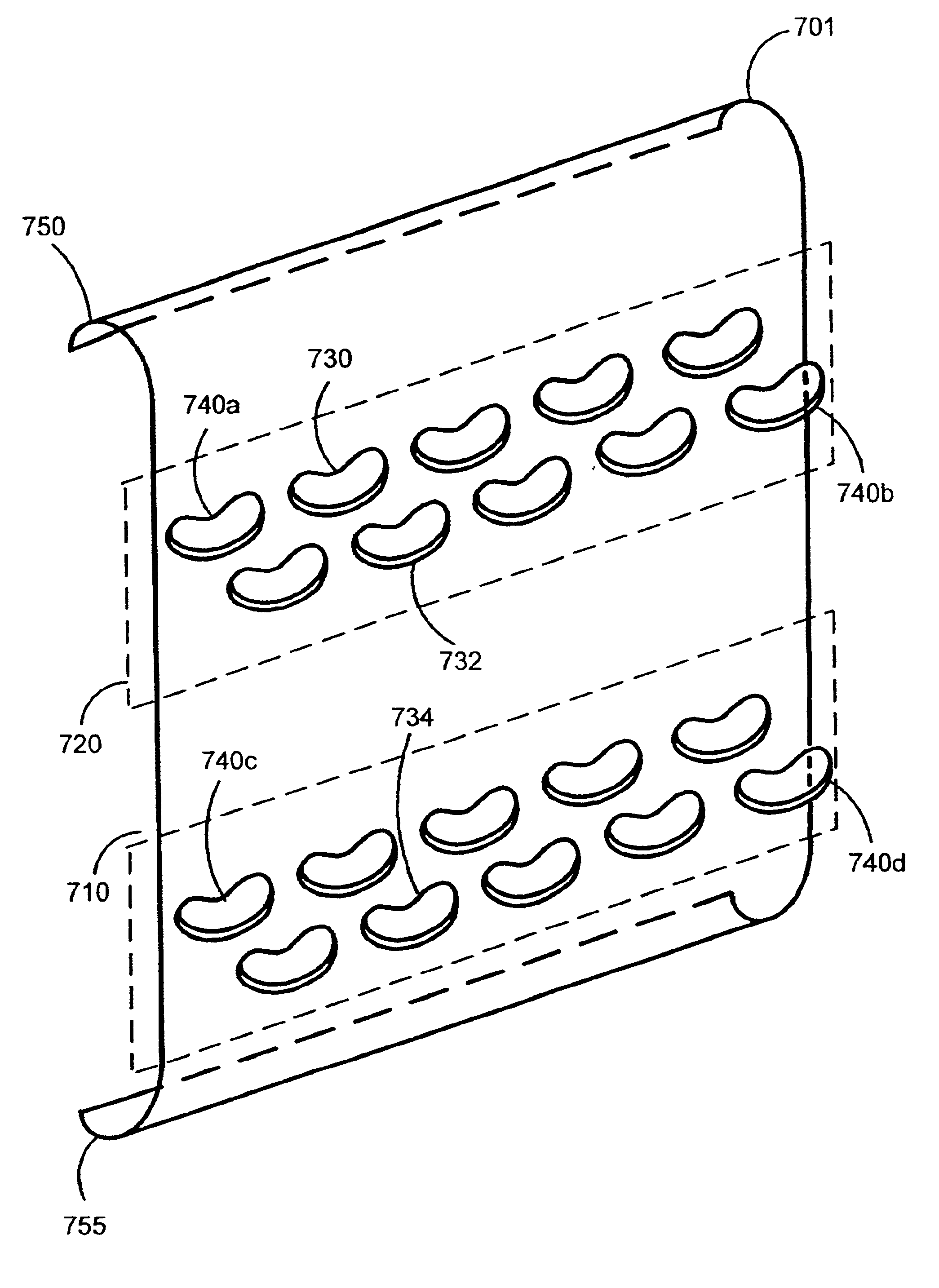
An antenna array comprising a ground plane and a plurality of elements mounted thereon, said elements being capable of emitting and receiving ultra wideband emissions. Elements are arrayed on the ground plane in two parallel rows, a transmitting row, and a receiving row, such that a given element in the receiving row is aligned in at least one direction with a corresponding element in the transmitting row. Additionally, the elements are configured on the ground plane to elicit a symmetrical product response in the azimuthal plane, and to produce horizontally polarized signals. An alternative embodiment places the elements with unique inter-element spacing within the rows. An embodiment comprises a fence structure between rows. A method for use comprises the step of transmitting a signal via an element in the transmitting row and receiving said signal through an element in the receiving row, not aligned with the transmitting element.

Description

CROSS REFERENCE TO RELATED APPLICATIONS[0001]This Application claims priority to U.S. Provisional Application Ser. No. 60 / 271,499, filed Feb. 26, 2001, and is a continuation of U.S. Non provisional Application Ser. No. 09 / 998,480, filed Nov. 30, 2001 now U.S. Pat. No. 6,667,724, which is incorporated by reference herein.BACKGROUND[0002]Law enforcement agencies often are confronted with hostage situations where armed intruders are barricaded inside a building. Officers on the scene generally have no means for determining the number and position of persons within the building, and are thus hampered in their efforts to resolve the situation. Similarly, law enforcement personnel planning a surprise raid on an armed compound would also greatly benefit from information related to the number and position of persons within. Such situational awareness decreases the amount of risk faced by the entering law enforcement personnel by decreasing the amount of unknowns. Furthermore, such a system ...

Claims


Application Information

Patent Timeline
IPC IPC(8): G01S13/00G01S13/02H01Q1/00H01Q1/52H01Q1/38H01Q21/08
CPCG01S13/0209G01S13/888H01Q1/38H01Q1/525H01Q21/08
Inventor BARNES, MARK A.GILBERT, CHARLES G.FLUHLER, HERBERT U.SCHANTZ, HANS G.NAG, SOUMYA K.DICKSON, DAVID M.
Owner HUMATICS CORP
Why Eureka
Try Eureka