Heat isolation and dissipation structures for optical components in photonic integrated circuits (PICs) and an optical transport network using the same

Active Publication Date: 2005-07-26
INFINERA CORP
View PDF5 Cites 20 Cited by
  • Summary
  • Abstract
  • Description
  • Claims
  • Application Information

AI Technical Summary

Benefits of technology

[0013]The vias forming the structure may be left unfilled, i.e., empty (thermal isolation) as well as being filled with a thermally conductive material, such as a metal (thermal dissipation). Unfilled structures serve a similar purpose to isolate the optical components as in the case of filled vias where the heat is efficiently carried away. In either case of filled or unfilled, the openings or vias comprising the structure, being positioned between adjacent optical components integrated in the PIC chip, greatly reduces any lateral thermal conductivity, so that on-chip optical components will not longer experience thermal association with neighboring or adjacent optical components.

Problems solved by technology

In either case of filled or unfilled, the openings or vias comprising the structure, being positioned between adjacent optical components integrated in the PIC chip, greatly reduces any lateral thermal conductivity, so that on-chip optical components will not longer experience thermal association with neighboring or adjacent optical components.

Method used


Image

  • Heat isolation and dissipation structures for optical components in photonic integrated circuits (PICs) and an optical transport network using the same
  • Heat isolation and dissipation structures for optical components in photonic integrated circuits (PICs) and an optical transport network using the same
  • Heat isolation and dissipation structures for optical components in photonic integrated circuits (PICs) and an optical transport network using the same

Examples


Embodiment Construction

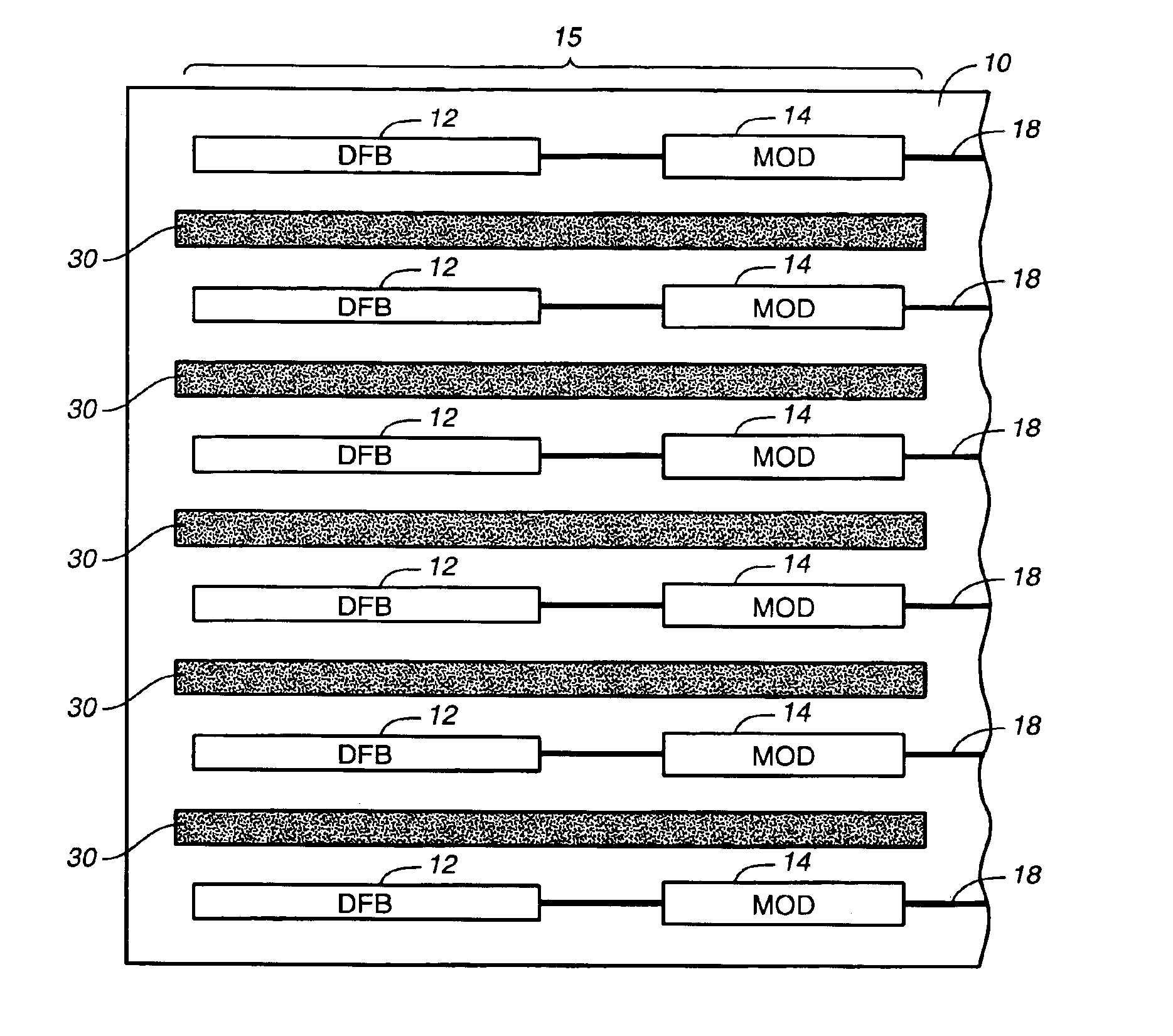
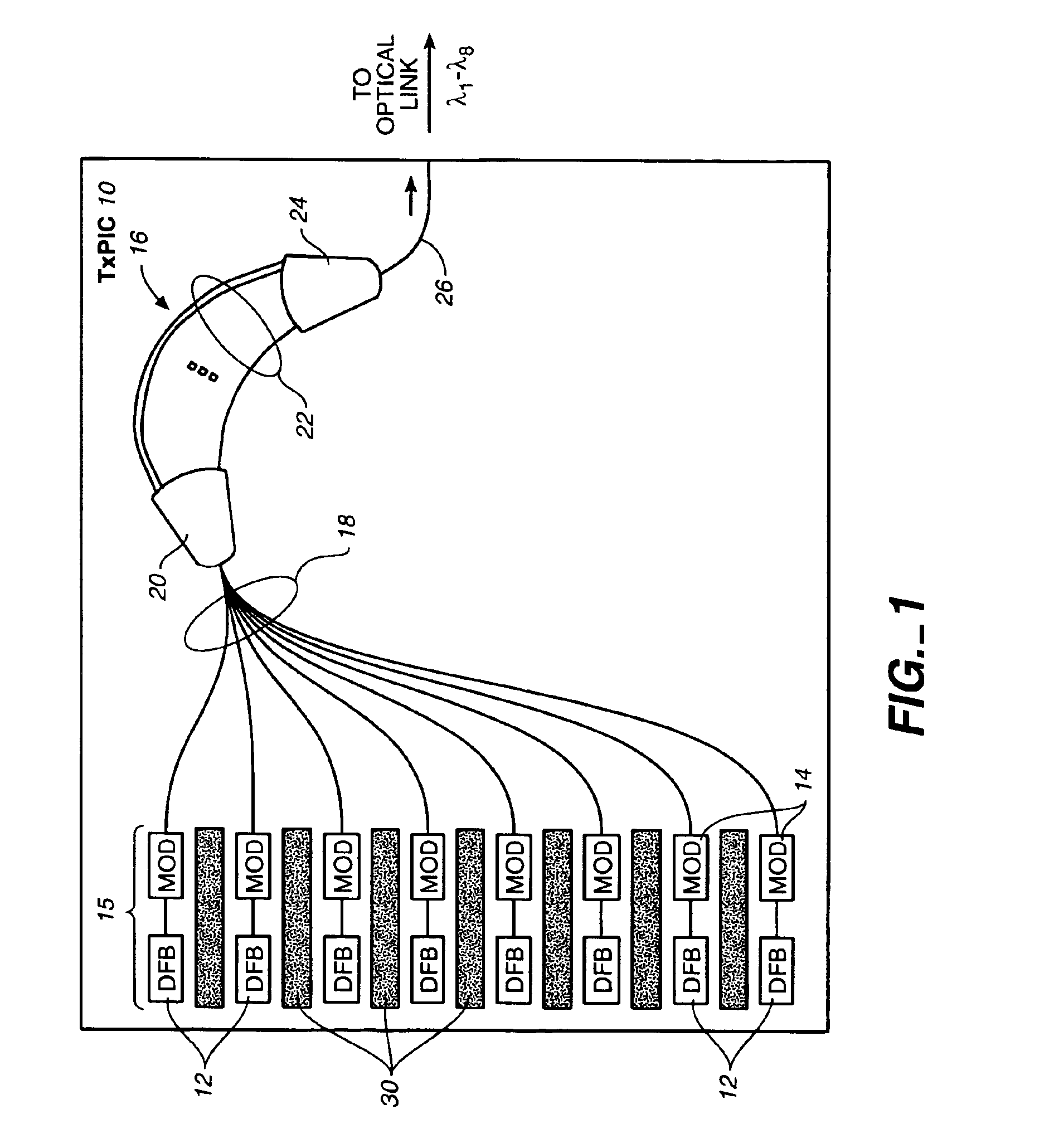
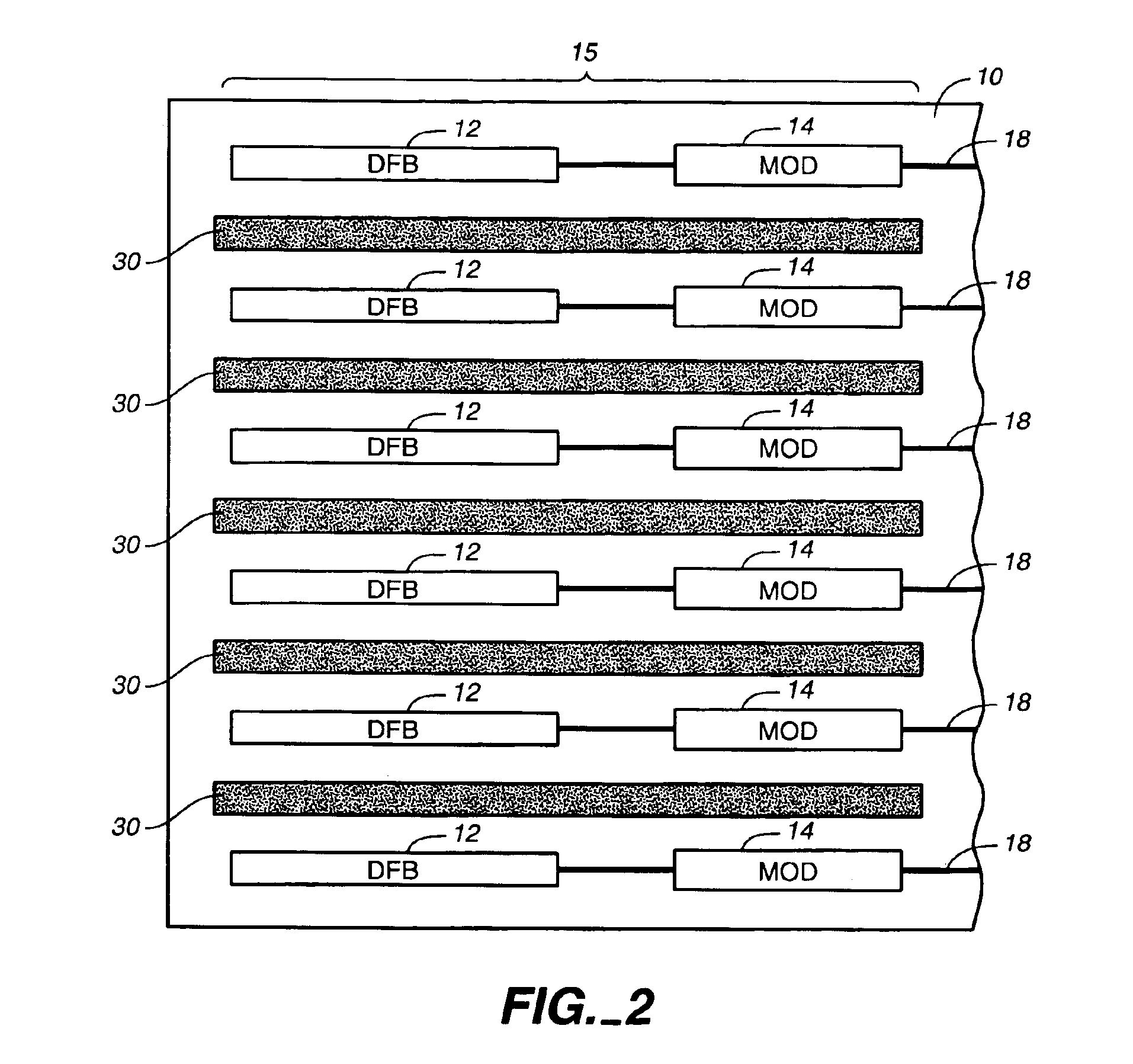
[0025]Reference is now made to FIG. 1 which illustrates one example of a PIC chip 10. The example shown in FIG. 1 is a transmitter photonic integrated circuit (TxPIC) chip, but it should be understood that in the employment of the thermal isolation / dissipation structure according to this invention, any PIC chip requiring thermal separation of neighboring optical components, whether active or passive types of such optical components, can be employed. While the invention herein may have its best functioning relative to thermal isolation or heat dissipation from between active optical components, i.e., components requiring an applied bias or current or other applied energy in order to perform a photonic function, it should be understood that the utility of this invention also extends to passive optical components, i.e., components that require no applied bias or current or other energy source to perform a photonic function, such as in cases, for example, where the passive optical compo...


PUM


Abstract

Photonic integrated circuits (PIC) semiconductor chips are provided with thermal isolation and / or heat dissipation structures between integrated optical components in the PIC chip, particularly integrated active optical components. These structures may also serve as a ground path for electrical circuitry on the PIC chip. An important function is the enhanced thermal isolation from, or dissipation of heat from, between adjacent or neighboring optical components in the PIC so that required spacing between adjacent optical components can be made even less than the thickness of the substrate thereby realizing a more compact optical component array on the monolithic PIC chips.

Description

CROSS-REFERENCE TO RELATED APPLICATION[0001]This application claims priority of U.S. provisional application, Ser. No. 60 / 350,218, filed Nov. 2, 2001, which application is incorporated herein by its reference.BACKGROUND OF THE INVENTION[0002]1. Field of the Invention[0003]This invention relates generally to photonic integrated circuit (PIC) chips and more particularly to thermal isolation and heat dissipation of integrated optical components formed in a PIC chip or in a wafer comprising PIC chip die.[0004]2. Description of the Related Art[0005]In a photonic integrated circuit (PIC), many active and passive optical components are integrated on the same semiconductor substrate. Some active photonic devices or components require large amounts of input power and, as a result, generate a substantial amount of heat in the chip. For example, arrays of laser diodes (LDs), electro-optic modulators and / or semiconductor optical amplifiers (SOAs) on a single PIC chip may require large amounts o...

Claims


Application Information

Patent Timeline
IPC IPC(8): G02B6/12H01S5/024H01S5/00G02B6/34H01S5/40H01S5/12
CPCG02B6/12004G02B6/12019G02B6/12026H01S5/024H01S5/0207H01S5/0268H01S5/12H01S5/4031
Inventor PETERS, FRANK H.NAGARAJAN, RADHAKRISHNAN L.
Owner INFINERA CORP
Why Eureka
Try Eureka