Eureka AIR delivers breakthrough ideas for toughest innovation challenges, trusted by R&D personnel around the world.

Street grid for surface drainage

a street grid and surface drainage technology, applied in the direction of paving details, water/sludge/sewage treatment, sewerage structures, etc., can solve the problems of affecting the drainage system in general, affecting the safety of pedestrians, and causing problems such as the inability to prevent differences to some extent,

Inactive Publication Date: 2005-12-08
ACO SEVERIN AHLMANN GMBH & CO KG
View PDF11 Cites 6 Cited by
  • Summary
  • Abstract
  • Description
  • Claims
  • Application Information

AI Technical Summary

Benefits of technology

[0006] It is an object of the present invention to provide a street grid of the kind cited at the outset which overcomes or substantially mitigates the aforementioned drainage problem.
[0008] A street grid for surface drainage in accordance with the present invention has substantial advantages. It is no longer crucial for the functionality of the drainage system that the upper edge of the frame be precisely level with, or below, the height of the bottom of the input channel. Because the water also flows away through the inlet openings formed at the upper edge of the frame, with the present invention water can continue to flow into the drainage system even if the level of the channel is below that of the upper edge of the street grid. In the case of level differences between the input and the street grid, therefore, the drainage performance is no longer thereby restricted. Hence the problem of formation of residual puddles no longer presents any danger, because the water does not build up at the edge of the street grid and in whatever hollows have been formed by settling, but instead can be conducted away through the recessed openings in the upper edge of the street-grid frame. As a result, not only is the working life of the drainage channel increased; instead, this design principle also produces distinct savings with respect to the costs of maintenance, cleaning and sanitation, or reconstruction. Unpleasant, in some cases even dangerous water-covered areas in front of the street grid are avoided, because the water is efficiently carried away despite subsidence of the input channel.
[0009] With an embodiment in which the approaching water flows into the street grid over the upper edges of frame and grating, in addition the risk of blockage of the grid is reduced, because no solid materials become caught between frame and grating so that they could obstruct the drainage system; the functional reliability is distinctly increased.
[0010] The inlet openings can be chosen arbitrarily, regarding their nature and construction. However, it is especially advantageous to construct the inlet openings on both the frame and, where desired, the grid as recesses. This reduces to a particularly great degree the risk of blockage of the drainage arrangement by solid materials or cohesive particles in the water that is to be drained; deposited solids are swept away when the next relatively large discharge of water occurs. Cleaning of inlet openings that have been clogged by external, mechanical actions, such as stones wedged in by pedestrians, is also considerably simplified.
[0012] It is also advantageous for the grating and frame inlet openings to slant downward towards the interior. This ensures a particularly effective entry because the water, which sometimes flows to the grid very slowly, is speeded up as it flows into the grid, so that the deposition of solid materials is prevented.
[0013] Another advantageous design of the invention is achieved by arranging the grating and frame inlet openings off-center in the region of the bottom of the channel. The advantage here is that fixing elements present on the grating, which are usually disposed in the middle, are protected from dirt. Furthermore, a statically required web is frequently present along the middle axis of gratings. When the inlet openings are arranged apart from the middle axis, no expensive reconstruction needs to be undertaken in gratings of known design. This considerably reduces the manufacturing costs and contributes to a broad area of application.

Problems solved by technology

Because of unpredictable features of the ground structure, overloading or design deficiencies, such differences are to some extent unavoidable.
These residual puddles are problematic and dangerous both for pedestrians and also for traffic flow.
Furthermore, they also result in damage to the drainage system in general.
If the water in the puddles freezes, very large pressures are generated especially at the junctions between channel and adjacent surface, for example a sidewalk; these forces can enlarge the gaps at the junctions and thus loosen the seating of the whole drainage channel, so that eventually the structure is destroyed.
Especially in the case of grids such that the water primarily flows away between frame and grating, these suspended masses rapidly cause blockages that in this case, because of their awkward positions, can be cleared only by hand or with high pressure.
A self-cleaning process is hardly to be expected here.

Method used


Image

  • Street grid for surface drainage
  • Street grid for surface drainage
  • Street grid for surface drainage

Examples


Embodiment Construction

[0024] In the following description, the same reference numerals are used for identical parts or parts with identical actions.

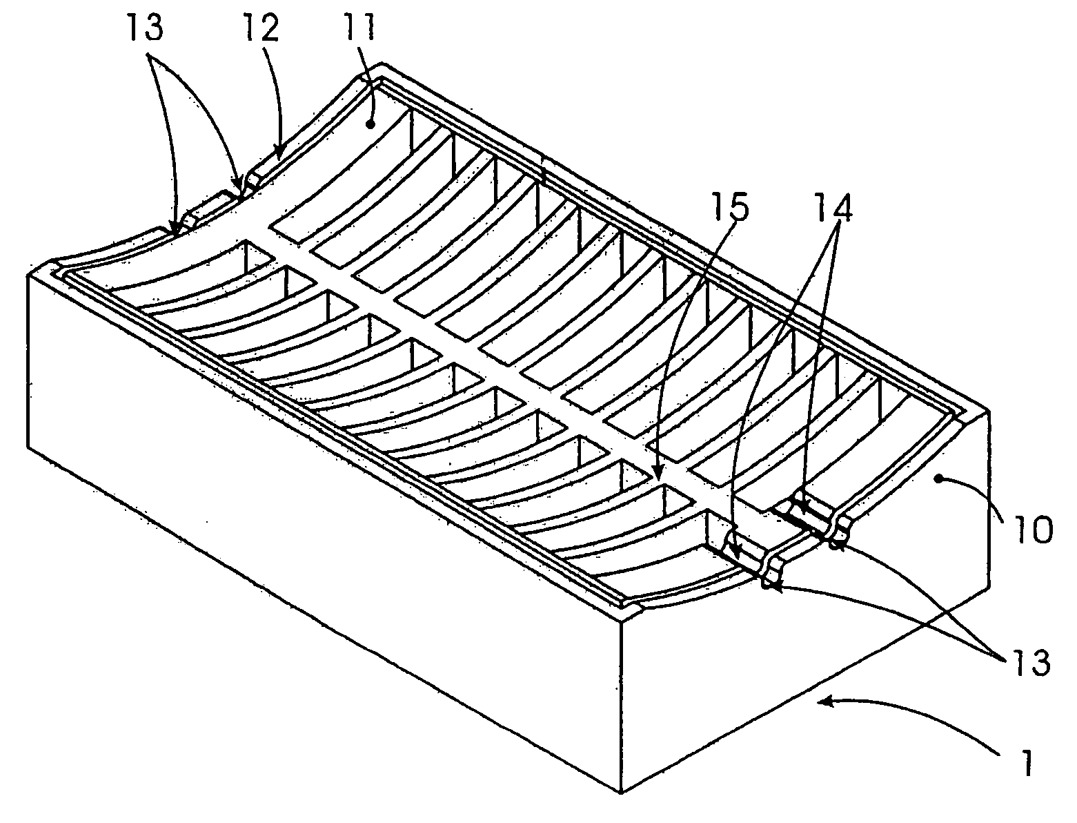
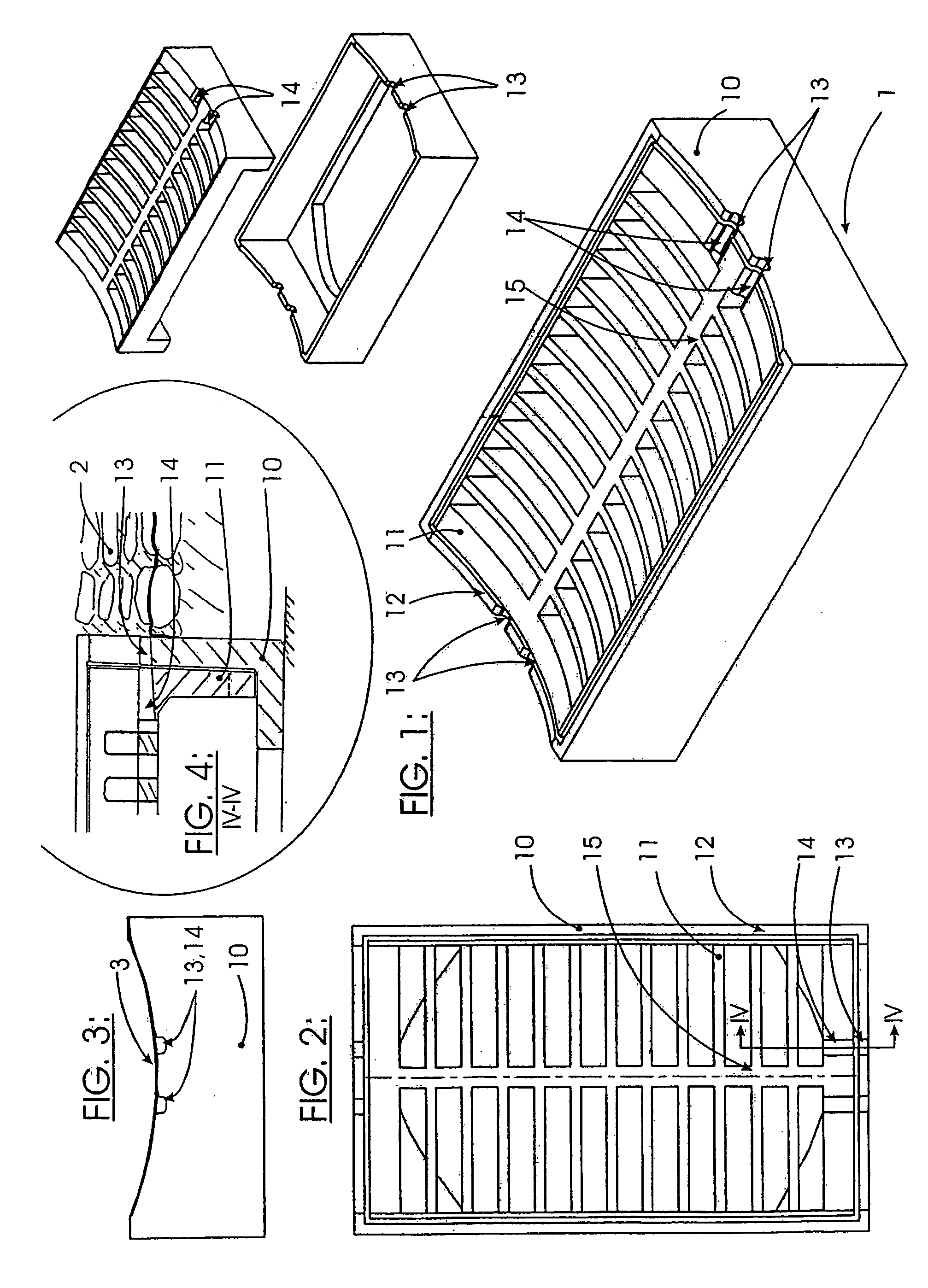
[0025]FIG. 1 is an isometric drawing of a street grid 1 consisting of a frame 10 and a grating 11 that is set into the frame 10. A frame upper edge 12 and the upper edge of the grating 11 are at the same level, as is made clear in FIG. 1. At the side wall of the frame 10 that leads in the flow direction, frame inlet openings 13 are formed in the frame upper edge 12, i.e. recesses in the frame. The grating 11 exhibits correspondingly shaped grating inlet openings 14. In a first exemplary embodiment of the invention the grating inlet openings 14 are positioned on the end face of the street grid 1, against which an input drainage channel 2 abuts. Water flowing toward the grid is, in the normal case, conducted into the street grid by way of the frame upper edge 12 and the upper edge of the grating 11. Now if there should be settling of the input channel 2, for i...


PUM


Abstract

A street grid is provided for surface drainage. The grid includes a frame and a grating, which are adapted to the contours of a paved gully in order to be integrated into the latter, for draining water that flows towards the street grid in a pre-defined flow direction. The aim of the grid is to ensure permanent drainage. To achieve this, recessed inlet openings are provided in the upper edge of at least one lateral wall of the frame in order to guide the water in the flow direction.

Description

CROSS-REFERENCE TO RELATED APPLICATIONS [0001] This application is a continuation of International Application No. PCT / EP2004 / 001364, filed Feb. 13, 2004, which was published in the German language on Aug. 26, 2004, under International Publication No. WO 2004 / 072392 A1 and the disclosure of which is incorporated herein by reference.FIELD OF THE INVENTION [0002] The invention relates to a street grid for surface drainage consisting of a frame and a grating that are adapted to the contours of a paved gully in which they are to be installed, in order to drain away water that flows toward the street grid in a predetermined direction. BACKGROUND OF THE INVENTION [0003] Such street grids for surface drainage are known and as a rule are installed in such a way that the surface of the frame and the surface of the grating are flush with the upper edge of the paved gully. Water flowing toward the street grid within the gully, derived for example from rain or melting snow, then enters the stre...

Claims


Application Information

Patent Timeline
Patent Type & Authority Applications(United States)
IPC IPC(8): E03F5/06
CPCE03F2005/068E03F5/06
Inventor MESSERSCHMIDT, HEINOSIEBER, MICHAEL
Owner ACO SEVERIN AHLMANN GMBH & CO KG
Why Eureka
Eureka Blog
Learn More