Methods and systems for marring fiber optic substrates

Active Publication Date: 2005-07-26
LUMITEX
View PDF4 Cites 12 Cited by
  • Summary
  • Abstract
  • Description
  • Claims
  • Application Information

AI Technical Summary

Benefits of technology

[0009]In accordance with another aspect of the invention, a non-uniform or variable abrasive surface may be provided on the roller. Also, the roller may be indexed to a predetermined rotational orientation and the roller and support positioned in a predetermined relative lengthwise starting position prior to causing the roller to press the substrate against the support and moving the roller and support lengthwise relative to one another to obtain an easily repeatable marring pattern on the substrate.

Problems solved by technology

Increased surface marring results in increased light emission.

Method used


Image

  • Methods and systems for marring fiber optic substrates
  • Methods and systems for marring fiber optic substrates
  • Methods and systems for marring fiber optic substrates

Examples


Embodiment Construction

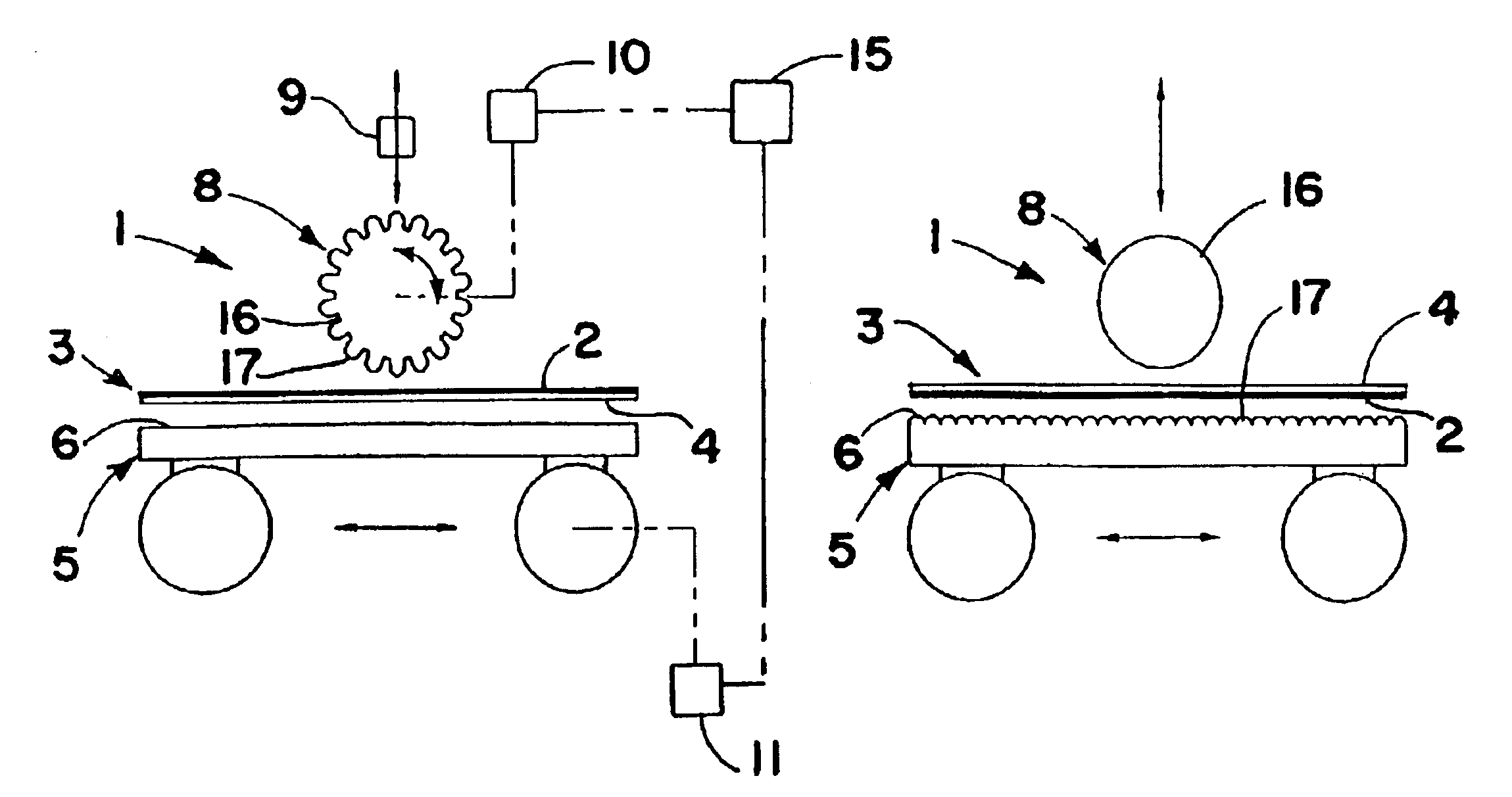
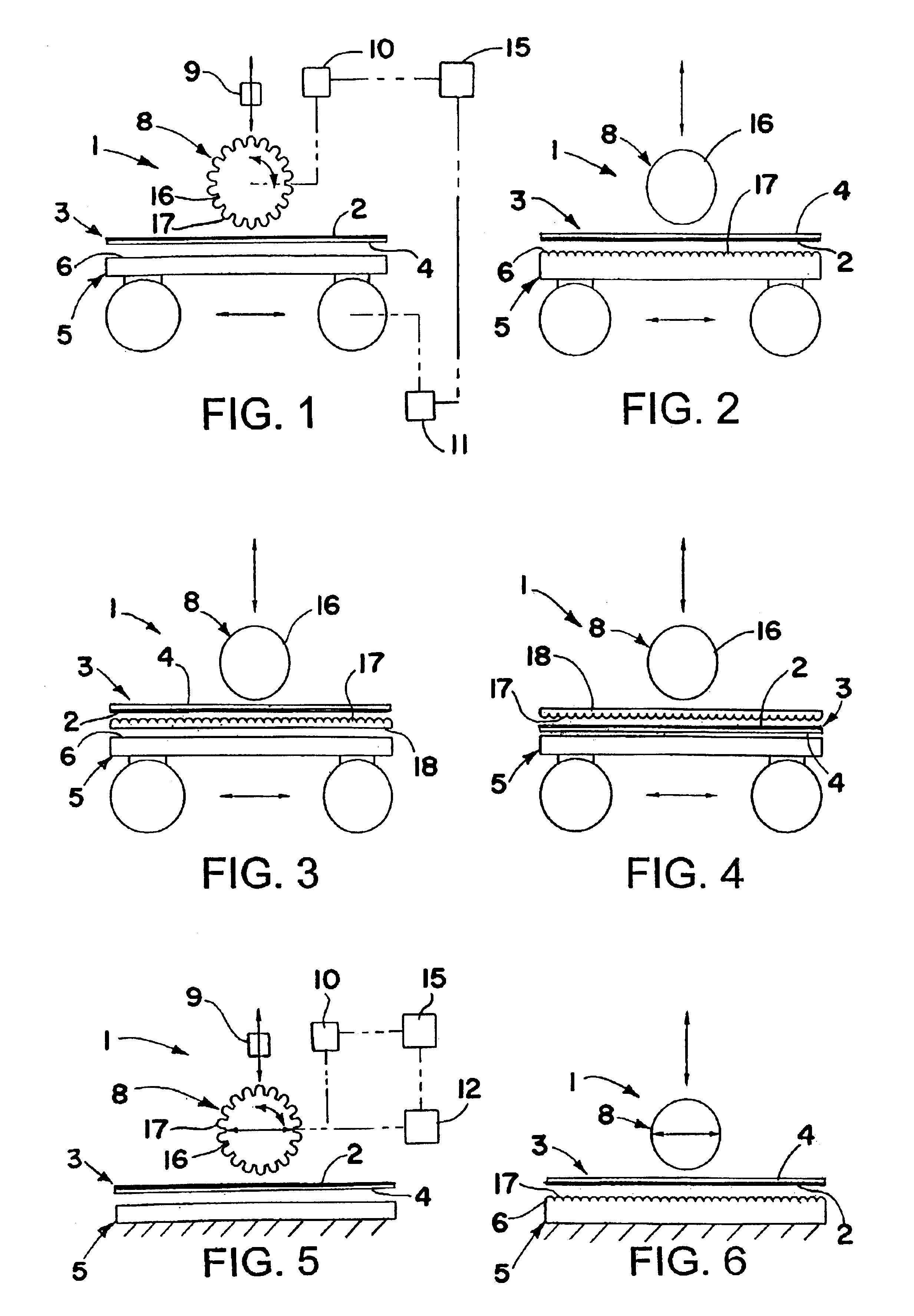
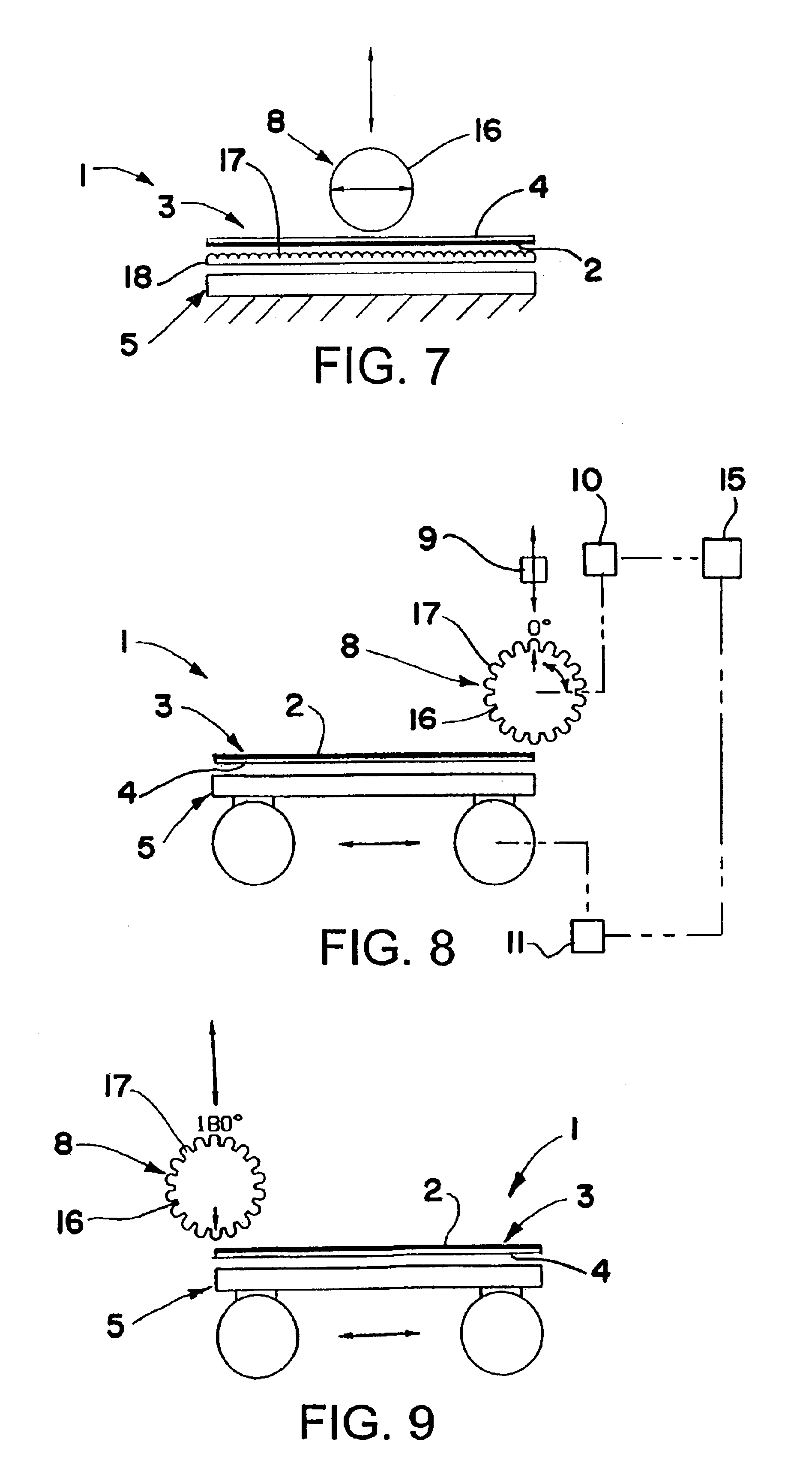
[0020]Referring now in detail to the drawings and initially to FIG. 1, there is schematically shown a system 1 in accordance with the invention for marring the surface of optical fibers 2 of a fiber optic substrate 3 for causing light applied to one or both ends of the optical fibers to be emitted from the marred surface areas thereof. The substrate 3 may be comprised of a plurality of such optic fibers 2, only one of which is shown, adhered to a suitable backing 4 which may for example be a plastic, generally reflective, sheet. The surfaces of other light guides including fiber optic rods and transparent plastic films, sheets or plates may also be marred in accordance with the invention similar to fiber optic substrates to create illuminators having a desired illumination pattern.

[0021]System 1 includes an elongate support 5 having a generally flat support surface 6 for supporting a length of the fiber optic substrate 3 thereon. One or more rollers 8 supported for example by an act...


PUM

PropertyMeasurementUnit
Lengthaaaaaaaaaa
Pressureaaaaaaaaaa
Abrasiveaaaaaaaaaa

Abstract

Methods and systems for marring the surface of a fiber optic substrate by pressing a length of the substrate against an elongate support with at least one roller and causing relative lengthwise movement between the roller and support with the roller pressing the substrate against the support and the roller rolling along the substrate. One of the roller and support may have an abrasive surface for marring the substrate during such relative lengthwise movement between the roller and support. Alternatively, the abrasive surface may be on a sheet supported by the support.

Description

FIELD OF THE INVENTION[0001]This invention relates to various methods and systems for marring the surface of fiber optic substrates to create fiber optic illuminating devices.BACKGROUND OF THE INVENTION[0002]Fiber optic substrates can be made into illuminating devices by marring or abrading (hereinafter collectively referred to as “marring”) the surface of the optical fibers at various points along their length to cause a portion of the light applied to one or both ends of the optical fibers to be emitted from the marred surface areas. Such illuminators may be used for example for display lighting, back lighting, front lighting and / or ornamental lighting and the like.[0003]Increased surface marring results in increased light emission. Accordingly, the intensity of the light emitted along the length of the substrates can be varied by varying the density or aggressiveness of the surface marring.[0004]It is generally known to mar fiber optic substrates by stamping, machining, molding, ...

Claims


Application Information

Patent Timeline
IPC IPC(8): F21V8/00G02B6/00
CPCG02B6/00G02B6/001Y10S385/901
Inventor PAGE, DAVID J.
Owner LUMITEX
Why Eureka
Try Eureka