Backlight module

Active Publication Date: 2005-02-24
AU OPTRONICS CORP
View PDF9 Cites 4 Cited by
  • Summary
  • Abstract
  • Description
  • Claims
  • Application Information

AI Technical Summary

Benefits of technology

[0016] According to the present invention, the light filter is disposed on the input surface of the light guide plate directly, and is capable of completely filtering out ultraviolet rays. Moreover, by forming a light-filtering oxide on the light guide plate or adhering a filter film on the second plate. The method of the present invention is less complicated, easily repeatable and reduces costs.

Problems solved by technology

The disclosed method complicates production and is still unable to completely filter ultraviolet rays.

Method used


Image

  • Backlight module
  • Backlight module

Examples


Embodiment Construction

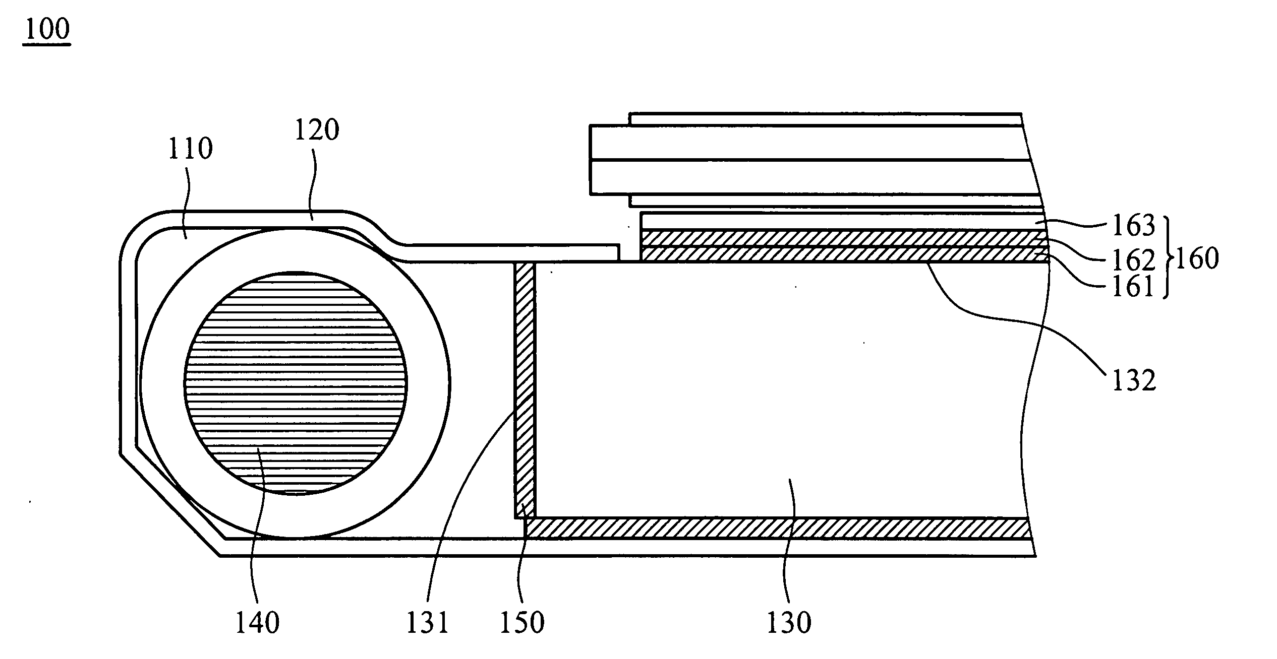
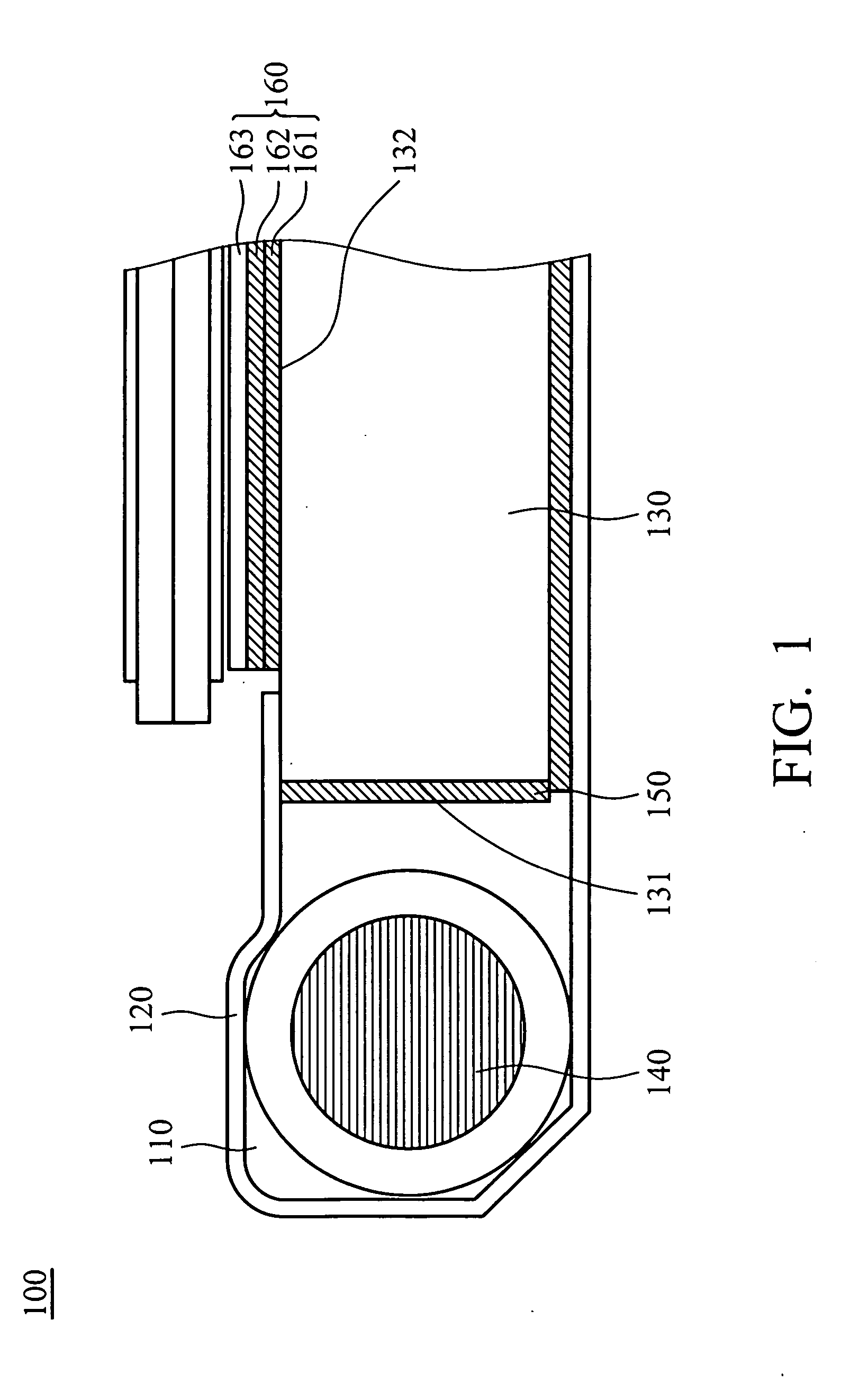
[0019]FIG. 1 shows a schematic view of a first embodiment in accordance with the present invention. The backlight module 100 has a first plate and a second plate forming a spacer 110. In the embodiment, the first plate is a reflector plate 120 and the second plate is a light guide plate 130. The light guide plate 130 has an input surface 131 and an output surface 132. The lamp 140 serving as the light source is disposed in the spacer 110. Light emitted from the lamp 140 spreads through the input surface 131 and into the light guide plate 130, and passes through the output surface 132 and out of the light guide plate 130.

[0020] To filter ultraviolet rays out of light, a light filter is disposed on the input surface 131 of the light guide plate 130. In the embodiment, the light guide plate can be a filter film 150 directly adhered to the input surface 131. The light guide plate also can be a UV filtering oxide (such as magnesia) formed on the input surface 131 to completely filter ul...


PUM


Abstract

A backlight module. The backlight module includes a spacer, a light source and a light filter. The spacer is formed by a first plate and a second plate. The light source is disposed in the spacer and emitted light which spreads through the second plate and out of the backlight module. The light filter is disposed on the second plate to filter ultraviolet rays.

Description

BACKGROUND OF THE INVENTION [0001] 1. Field of the Invention [0002] The present invention relates to a backlight module and in particular to a backlight module directly filtering ultraviolet rays. [0003] 2. Description of the Prior Art [0004] Conventionally, a backlight module is provided with light-filtering to prevent color distortion of the backlight module. In detail, the light tube of the backlight module is generally coated with a light-filtering material, such as magnesia, to filter out ultraviolet rays thereby preventing color distortion. [0005] The disclosed method complicates production and is still unable to completely filter ultraviolet rays. SUMMARY OF THE INVENTION [0006] In order to address the disadvantages of the aforementioned backlight module, the present invention provides a backlight module disposed on an input surface of a light guide plate capable of directly filtering ultraviolet rays. [0007] The backlight module includes a spacer, a light source and a light ...

Claims


Application Information

Patent Timeline
IPC IPC(8): F21V8/00G02B6/00
CPCG02B6/0051G02B6/0026
Inventor LIN, YA-LAN
Owner AU OPTRONICS CORP
Why Eureka
Try Eureka