Optical measurement of vane ring throat area

a technology of optical measurement and throat area, which is applied in the direction of instruments, liquid fuel engines, motors, etc., can solve the problems of unreliable conventional gas flow area measurement with comparator methods, significant local pressure effects, and high cost of stator rings

Active Publication Date: 2006-10-03
PRATT & WHITNEY CANADA CORP
View PDF17 Cites 18 Cited by
  • Summary
  • Abstract
  • Description
  • Claims
  • Application Information

AI Technical Summary

Problems solved by technology

However, generally hundreds of minute bends or adjustments must be performed around the stator ring, which accumulate to affect the flow area of the stator.
As well, although flow rigs provide reliable results when stator blades are relatively new and regular, once a worn stator is used with rework or adjustments made to the leading or trailing edges, local pressure effects create significant inaccuracies.
In cases where the stator ring has been refurbished, subjected to wear and tear, or has been adjusted excessively, conventional gas flow area measurement with comparator methods are unreliable.
A stator ring is an extremely expensive component and therefore an accurate reliable means of measuring the flow area is required.
Mechanical measuring devices may be imprecise, slow and relatively expensive.
However, deviations are common in all but new parts since vane adjustments, refurbishment and normal wear cause profile deviation, chord length deviation or both.
Therefore the deviations are not entirely missed by the tracing probe, although a degree of error is introduced.

Method used


Image

  • Optical measurement of vane ring throat area
  • Optical measurement of vane ring throat area
  • Optical measurement of vane ring throat area

Examples


Embodiment Construction

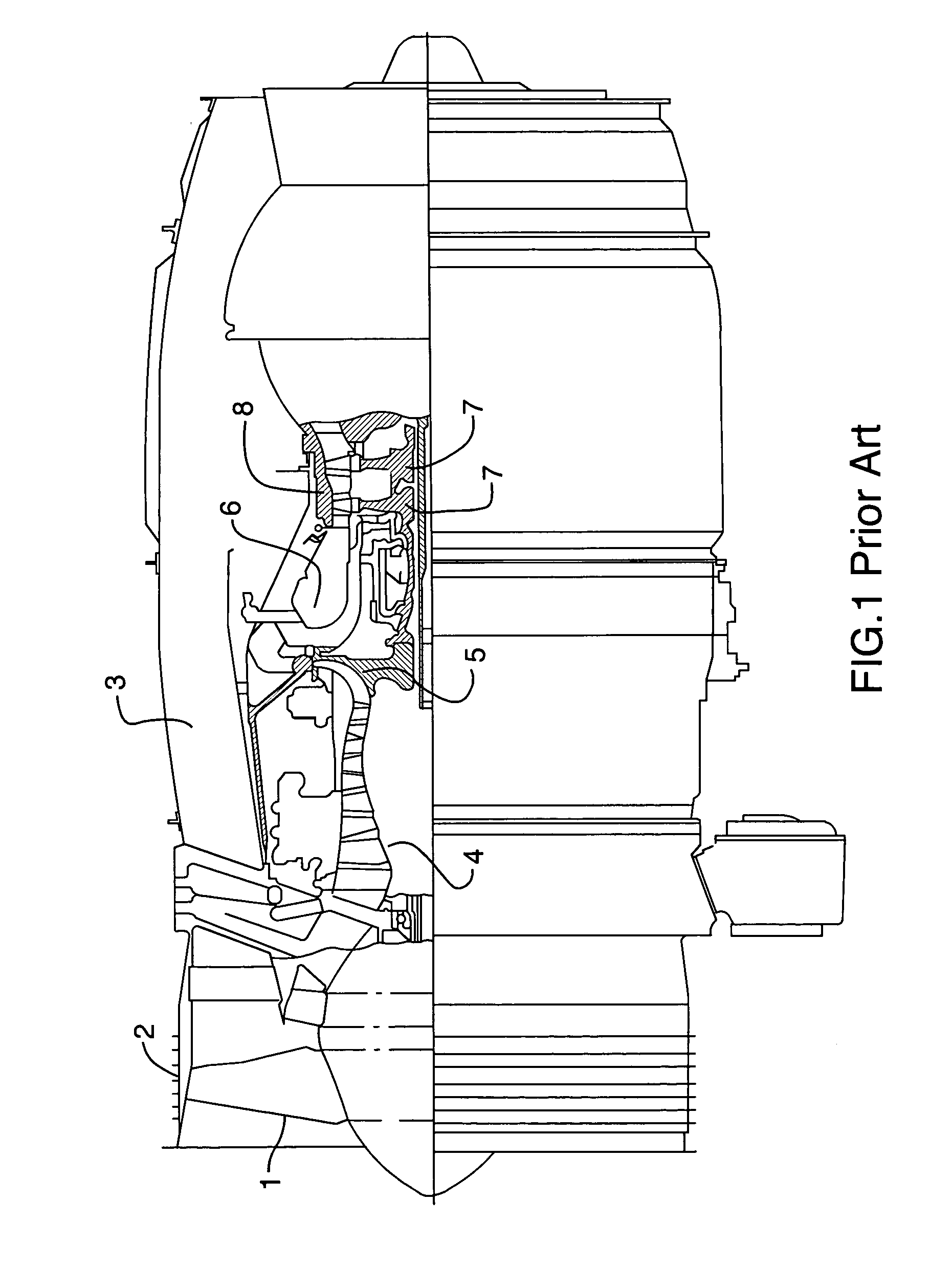
[0023]FIG. 1 shows a typical axial cross-sectional view through a turbofan engine, although the invention is equally applicable to turbo shaft and turboprop engines. Intake air passes over rotating fan blades 1 within the fan casing 2 and is split into a bypass flow that progresses through bypass duct 3 and the internal engine core. The internal portion of the airflow passes through low-pressure axial compressor 4 and centrifugal compressor 5 into the combustor 6. Fuel is injected and ignited within the combustor 6 and hot gases pass over turbines 7 to be ejected through the rear exhaust portion of the engine

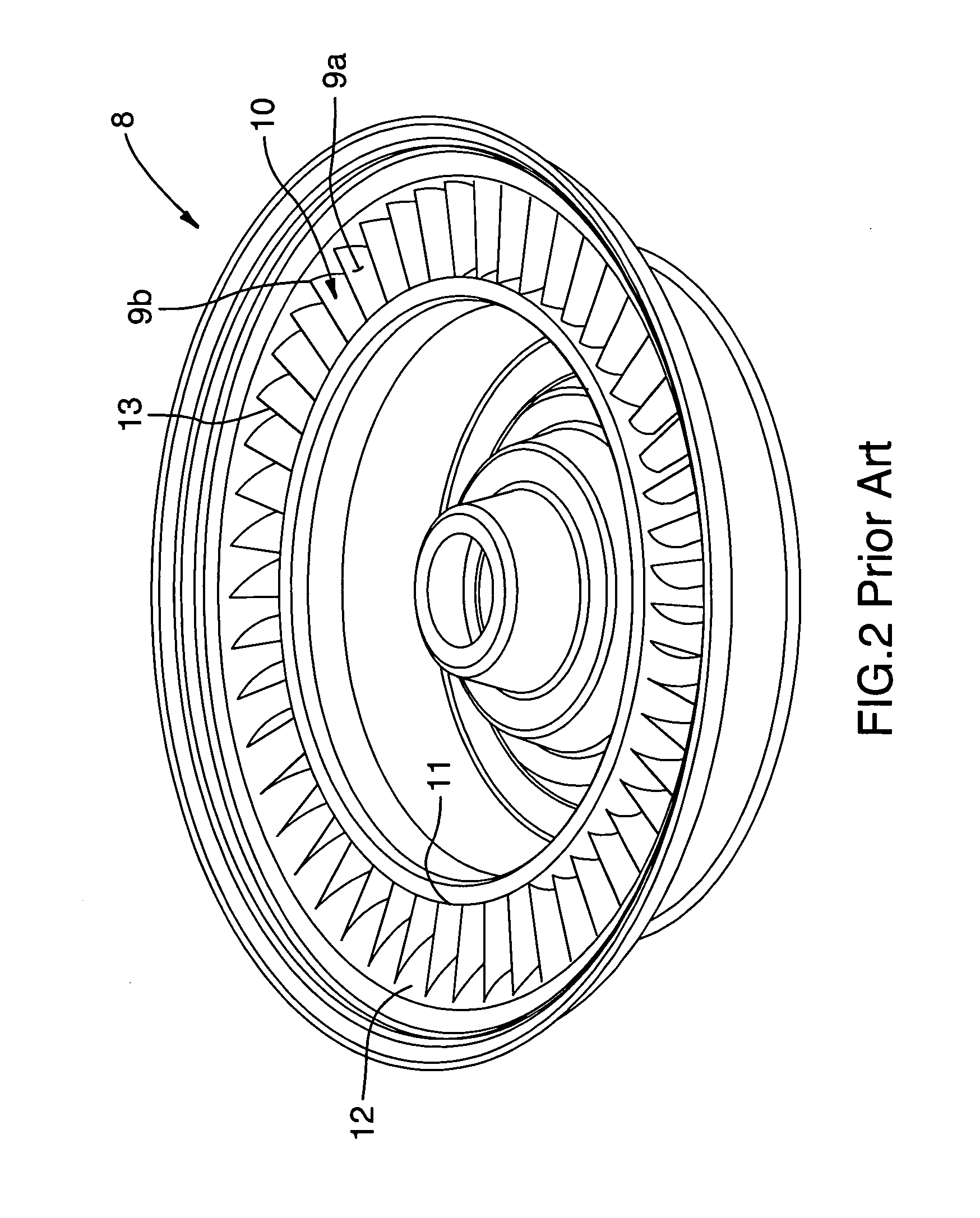
[0024]FIG. 2 illustrates a perspective view of a single vane ring 8 that is conventionally disposed upstream of the turbines 7 or upstream of compressor turbines in an axial flow compressor 4.

[0025]The vane ring 8 has an annular array of stator vanes 9 that define a plurality of individual throats 10 between each set of adjacent vanes 9. The detailed views in FIG. 5 and FIG. 6 i...


PUM


Abstract

A method and device for optically measuring throat area in a vane ring for a gas turbine engine, the method according to one aspect of the invention following the steps of: placing the vane ring on a fixture with the periphery of each throat within an optical measuring field of view; positioning a primary radiation source to cast an area of shadow on the vane ring delineating the throat as a dark area surrounded by an area of reflectance; capturing an image of the dark area with a radiation detector; analyzing the image to acquire a dimensional data of the dark area, proportional to the absolute value of throat dimensions; progressively capturing and analyzing images from each of the individual throats; then processing and calibrating the dimensional data of each image to account for scaling and viewing direction (perspective distortion) to acquire an absolute value for the composite throat area of the vane ring.

Description

TECHNICAL FIELD[0001]The invention relates to a method of optically measuring the throat area of a vane ring for a gas turbine engine, by irradiating or illuminating the vanes and shrouds bounding a selected throat, then measuring the resulting shadow area which corresponds with the throat area and repeating the process for each throat in a vane ring to determine the total vane ring throat area.BACKGROUND OF THE ART[0002]The invention relates to a method and a device for measuring the flow area at the point of maximal restriction in a gas flow passage, in particular for measuring the vane or nozzle area of a gas turbine engine.[0003]Stators, also known as vane rings, are an array of stationary airfoils that are used to change the direction of an annular airflow as it approaches or departs from an array of rotating blades on a turbine or compressor rotor for example. In order to change the minimum flow area through a stator vane ring, adjustments to the trailing edge angle of stator ...

Claims


Application Information

Patent Timeline
Patent Type & Authority Patents(United States)
IPC IPC(8): G06K9/36G01B11/02G01B11/24G01B11/28
CPCG01B11/2433G01B11/285
Inventor LEBOEUF, PIERRE
Owner PRATT & WHITNEY CANADA CORP
Why Eureka
Try Eureka