
Portable compact infusion device

a compact, infusion device technology, applied in the direction of infusion needles, instruments, other medical devices, etc., can solve the problems of small controllable infusion rate, and large size of infusion device, etc., to achieve safe use, convenient portability and low cos

Active Publication Date: 2021-06-15
ATDOSE CO LTD
View PDF8 Cites 0 Cited by
  • Summary
  • Abstract
  • Description
  • Claims
  • Application Information

AI Technical Summary

Benefits of technology

The present invention is a small and portable infusion device that can be used safely and as an alternative to intravenous drip. It allows for the continuous and subcutaneous injection of a small amount of medication for long hours. The device is easy to use, inexpensive, and disposable, which helps prevent contamination and infection. It is also highly portable, with a weight of 10 grams or less. The technical effects of this invention include its size, weight, and ability to prevent leakage and infection.

Problems solved by technology

However, in the conventional technique related to the infusion device widely used in the medical field today, the minimum controllable infusion rate is limited, and even though a motor-controlled pump can finely control the infusion rate, the minimum limit of the controllable infusion rate is several tens to a hundred microliters per minute (μL / min).
Inevitably, the size of the infusion device becomes large, and as a result, various problems occur in reality at medical facilities or the like.
One of the issues to be improved in the medical field is the quality of life of the patients under medication.
A patient undergoing infusion therapy is required to be connected to the infusion tube for long hours, and the free movement of the patient is greatly restricted.
Another issue from a different viewpoint is the burden placed on medical workers.
As a result, the doctors and nurses are facing increased burden to prevent medical accidents.
Moreover, the price of the device itself tends to be high because of the motor structure, the control apparatus, or the like of the infusion device, and it should be admitted that today's infusion device has not been used widely by all the patients who need administration of infusion medication in everyday life including those at small clinics and the like.

Method used


Image

  • Portable compact infusion device
  • Portable compact infusion device
  • Portable compact infusion device

Examples


example 1

[Example 1] Production of Compact Infusion Device

[0262]A compact infusion device 1 having the components as described below was produced as one embodiment of the compact infusion device according to the present invention.

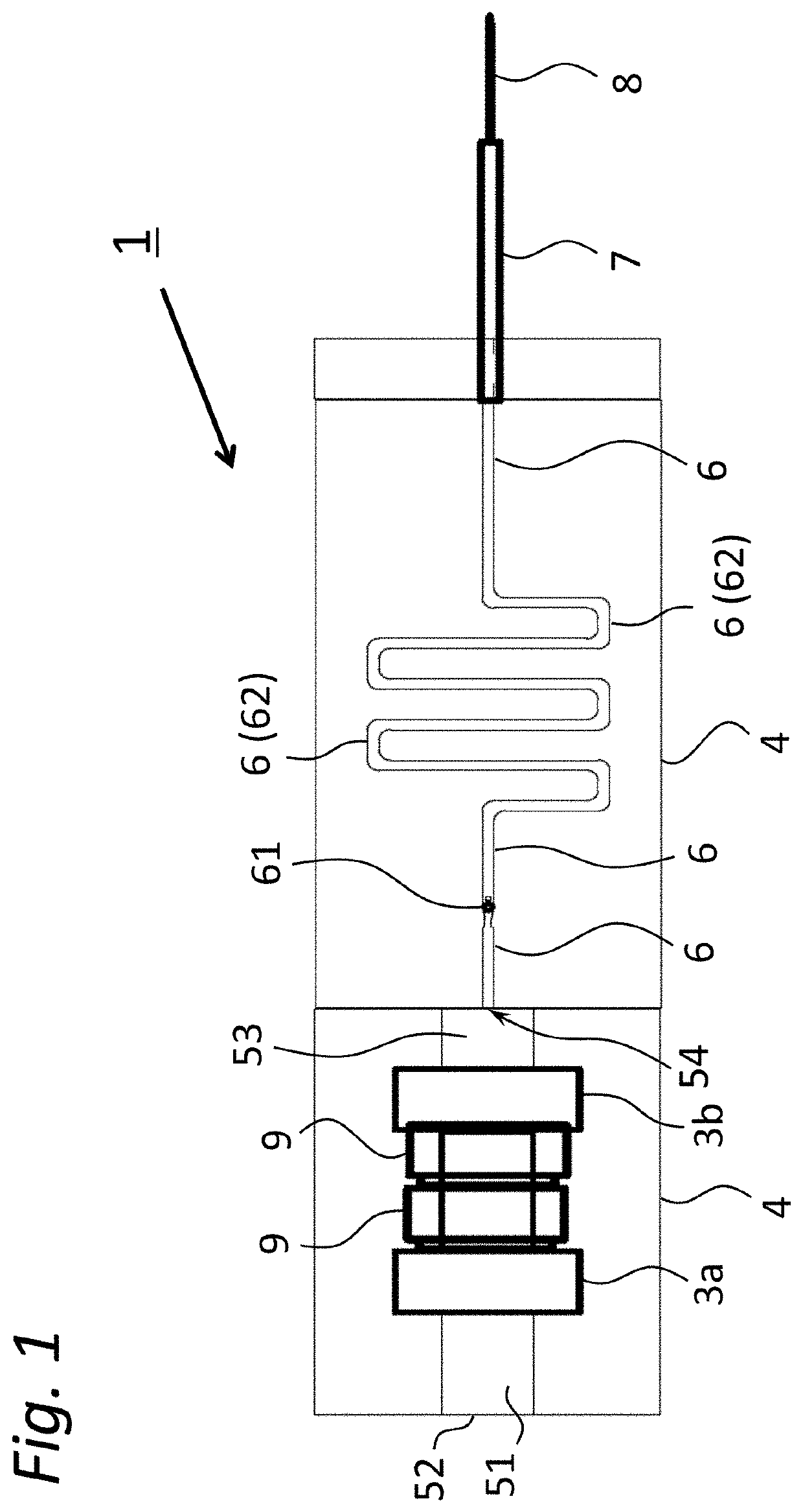
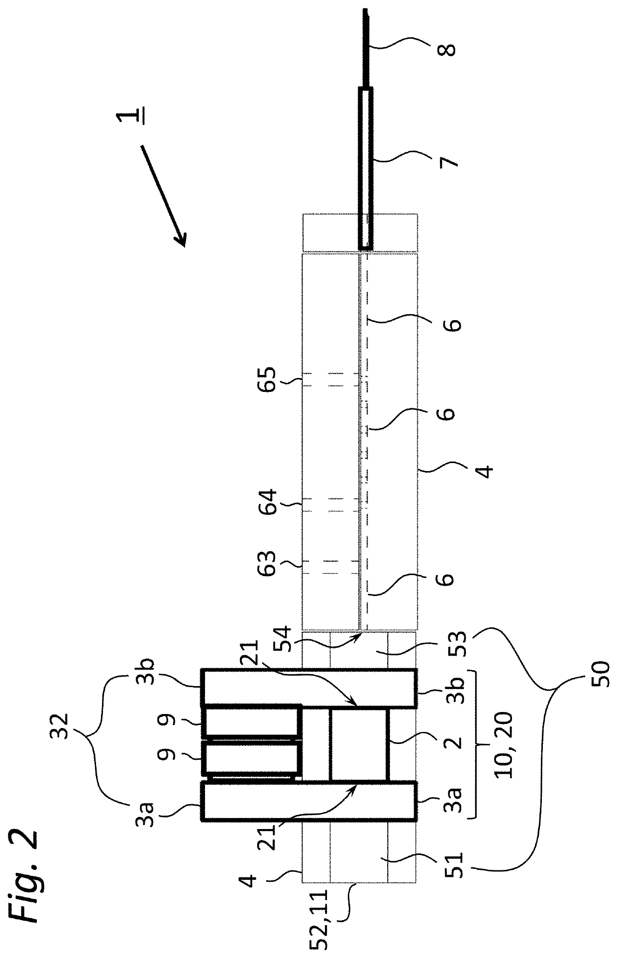
[0263]The device 1 in this example is a compact infusion device whose main components are the fluid drive 10, the fluid holding portion 50, the drug solution holding channel 6, and the needle holding portion 7 as described below.

[0264](1) Fluid Drive

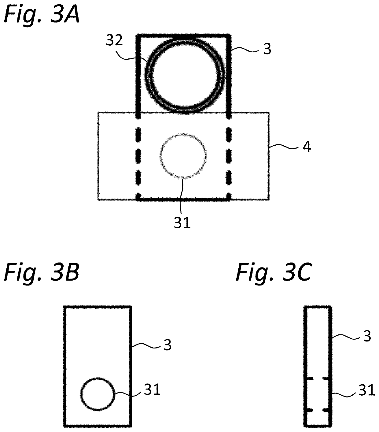
[0265]The fluid drive 10 of this device is a structural body in which the porous body 2 is sandwiched by the pair of rubber electrodes 3 containing carbon. In this device, the sandwiched structure 20 in which the porous body 2 is sandwiched by these electrodes serves as the electroosmotic flow pump that supplies fluid driving force to the drug solution holding channel 6.

[0266]The porous body 2 is a cylindrical member made of porous ceramic material, and in this device, the cylinder is placed lengthwise, such that its two...

example 2

[Example 2] Movement and Specifications of the Device

[0302]The movement and the like of the compact infusion device produced in the example above were examined.

[0303]In the compact infusion device produced in Example 1, the stopper members were removed from the openings of the drug solution introducing channel and the drug solution discharge channel, and a liquid sample was introduced into the drug solution holding channel through the opening of the drug solution introducing channel. When the liquid sample was filled until it overflowed from the opening of the drug solution discharge channel, the stopper members were attached to the two openings, and the openings were closed. Then, two CR1616 button cells (6 volts) manufactured by Hitachi Maxell Ltd. were inserted in series between the pair of rubber plate electrodes such that they fitted to the power supply support portions of the rubber electrodes, and the electroosmotic flow pump, which served as the fluid drive, was driven.

[0304...

example 3

[Example 3] Processing Example of the Device

[0306]Another compact infusion device different from the one produced in the example above was produced and subjected to trimming, and the movement and the like of this compact infusion device were examined.

[0307]A compact infusion device was produced following the procedures of Example 1, and the support was subjected to trimming. Here, the portions of the support unnecessary for the device were removed to reduce the weight of the device.

[0308]Then, the liquid sample was filled into the drug solution holding channel following the procedures of Example 2, three CR1616 button cells (9 volts) manufactured by Hitachi Maxell Ltd. were inserted in series between the pair of rubber electrodes such that they fitted to the power supply support portions of the rubber electrodes, and electroosmotic flow pump, which served as the fluid drive, was driven.

[0309]It was confirmed that, in the compact infusion device produced in this example, very small a...


PUM


Abstract

A compact infusion device that is easily portable and inexpensive, can be used safely, and can provide a technique alternative to intravenous drip. The portable compact infusion device includes a fluid drive, a fluid holding portion, a drug solution holding channel, and a support, wherein the fluid drive includes a porous body that allows generation of electroosmotic flow and a pair of rubber electrodes each containing electroconductive material and having a communicating portion, the porous body being sandwiched between the communicating portions of the pair of rubber electrodes to form a sandwiched structure.

Description

CROSS-REFERENCE TO RELATED APPLICATION[0001]This application is a Section 371 National Stage Application of International Application No. PCT / JP2018 / 015779, filed Apr. 17, 2018 and published as WO / 2018 / 194041 on Oct. 25, 2018, in Japanese, the contents of which are hereby incorporated by reference in their entirety.TECHNICAL FIELD[0002]The present invention relates to a portable compact infusion device. More particularly, it relates to a compact infusion device that is easily portable and inexpensive, can be used safely, and can provide a technique alternative to intravenous drip.BACKGROUND ART[0003]Intravenous drip (hereinafter, may be referred to as “IV infusion”) is a method for intravenously administering medication to the human or animal body and enables to slowly and gradually introduce medicine into the vein. Intravenous drip is widely used in the medical field, because the risk of sudden increase of the drug concentration in the blood can be avoided though the medication is ...

Claims


Application Information

Patent Timeline
Patent Type & Authority Patents(United States)
IPC IPC(8): A61M5/142A61M5/158A61M5/168
CPCA61M5/142A61M5/158A61M5/16886A61M2205/0233A61M2206/20A61M2005/14204
Inventor HIRAFUJI, MAMORU
Owner ATDOSE CO LTD
Learn More