Gateway for reducing delay jitter and method for data transfer therein

Inactive Publication Date: 2005-07-26
NTT DOCOMO INC
View PDF18 Cites 38 Cited by
  • Summary
  • Abstract
  • Description
  • Claims
  • Application Information

AI Technical Summary

Benefits of technology

[0016]The controller may obtain the time period to keep the first data unit by shortening a maximum delay time, which may occur in propagation of data units through the first network, on the basis of a permissible delay jitter at the destination terminal.
[0017]In accordance with another aspect of the present invention, a method for transferring data, may comprise: re

Problems solved by technology

Data propagation delays occur in networks due to various reasons, and delay times for data units may be different from each other.
This kind of unwanted variation in the propagation delay time is called delay jitter.
The causes of delay jitter may, for example, be the store-and-forward type exchange in a packet-switched network, packet or frame queuing at a node on the transmission path, or the fact that data units arrive at the gateway through different paths.
Even in a circuit-switched network, delay jitter is caused by si

Method used


Image

  • Gateway for reducing delay jitter and method for data transfer therein
  • Gateway for reducing delay jitter and method for data transfer therein
  • Gateway for reducing delay jitter and method for data transfer therein

Examples


first embodiment

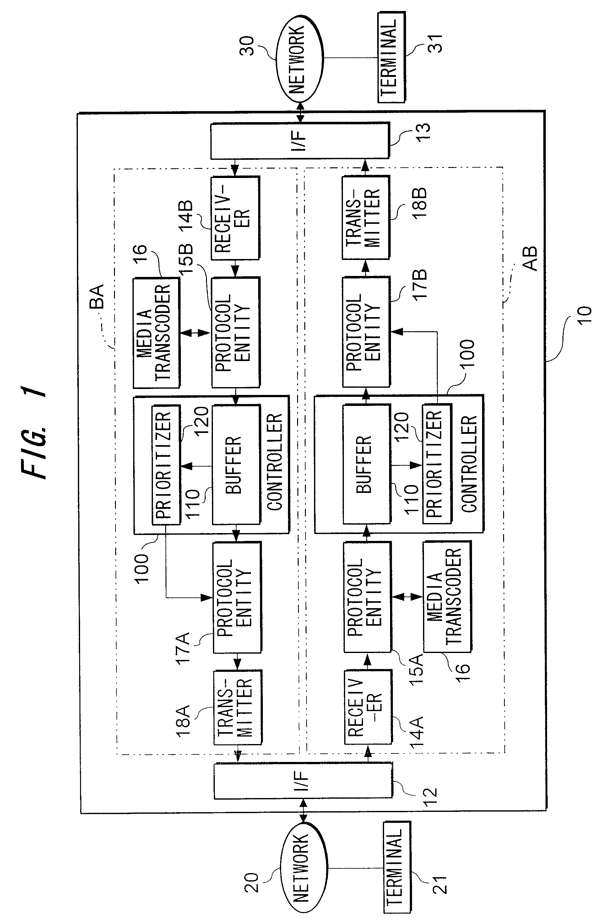
[0033]As shown in FIG. 1, in accordance with the present invention, a gateway 10 interconnects two networks 20 and 30, whereby data can be transmitted from a source terminal served by the network 20 to a destination terminal served by the network 30, and data can be transmitted from a source terminal served by the network 30 to a destination terminal served by the network 20. Although each of the networks 20 and 30 can serve a number of terminals, FIG. 1 represents only terminals 21 and 31 served by the networks 20 and 30, respectively as a matter of convenience. Within each of the networks 20 and 30, data units in one or various forms can be exchanged.

[0034]In this embodiment, the network 20 is a packet-switched network where data units are transported being encapsulated in packets while the network 30 is a circuit-switched network where data units are transported as frames to be multiplexed into one bit stream: the frames includes audio and video data frames. However, it is not in...

second embodiment

[0116]Assume in a second embodiment in accordance with the present invention in FIG. 15, both networks 20 and 300 are packet-switched networks, and the likely maximum delay jitter in the packet-switched network 20 is greater than that in the packet-switched network 30. In this case, if the source terminal is a terminal served by the network 20 and the destination terminal belongs to the network 300, it is advantageous that the gateway 10 absorbs a part, of the delay jitter, which has occurred in the source-side network 20, in accordance with the dejitterizing capability of the destination terminal 31 as similar to the above-described embodiment.

[0117]However, if the source terminal is a terminal served by the network 300 where likely delay jitter is smaller and destination terminal belongs to the network 20 where likely delay jitter is greater, and if the dejitterizing capability of the destination terminal is high, it may not be strictly necessary that the gateway 10 absorbs a part...


PUM


Abstract

A gateway for interconnecting two networks, comprising a receiver, a controller, and a transmitter. The receiver receives from a first network a plurality of data units in all least one form. The controller temporarily stores the data units received by the receiver and outputs the data units on the basis of the dejitterizing capability of a destination terminal served by a second network, thereby reducing jitter among delays of the data units. The transmitter sends data units corresponding to the data units output by the controller to the destination terminal through the second network.

Description

BACKGROUND OF THE INVENTION[0001]1. Field of the Invention[0002]The present invention relates to a gateway for connecting a network where data propagation delays vary with another network and a data transfer method suitable for the gateway.[0003]2. Related Art[0004]Gateways are the indispensable components in order to achieve multimedia communications between terminals connected to heterogeneous networks that use different protocols and have different network characteristics. This type of gateway receives data following the protocol for the network to which the source terminal belongs and transmits the data pursuant to the protocol used in the network to which the destination terminal belongs. Consequently, the data from the source terminal passes through the network to which the source terminal belongs, the gateway, and the network to which the destination terminal belongs.[0005]For multimedia communications, terminals complying with ITU-T Recommendation H.323 are commonly employed...

Claims


Application Information

Patent Timeline
IPC IPC(8): H04N7/24H04N7/62H04L12/64H04N7/52H04L29/06
CPCH04L12/6418H04N21/23406H04N21/2368H04N21/242H04N21/64707H04L65/104H04L65/80H04L65/103H04L29/06027H04L65/1101
Inventor MORIOKA, MASASHISUZUKI, TAKASHIKAWAHARA, TOSHIRO
Owner NTT DOCOMO INC
Why Eureka
Try Eureka