Vehicle compass compensation

a compass and compensation technology, applied in the field of vehicle compass compensation, can solve the problems of irregularities in the mounting of the compass and/or sensors, the variations or declinations of the earth magnetic field at any given location are generally not perfectly symmetrical, and the original calibration may later become less accura

Inactive Publication Date: 2005-08-02
DONNELLY CORP
View PDF51 Cites 139 Cited by
  • Summary
  • Abstract
  • Description
  • Claims
  • Application Information

AI Technical Summary

Benefits of technology

[0008]The present invention is intended to provide a fully automatic and continuous calibration system for vehicle compasses, which continuously calibrates the compass without requiring an initial preset of the vehicle magnetic signature or manual calibration of the compass.

Problems solved by technology

Additionally, as the deviating field may change over time, due to either a change in the magnetic signature of the vehicle or in the magnetic field surrounding the vehicle, an original calibration may later become less accurate.
In reality, however, irregularities may occur in the mounting of the compass and / or sensors in the vehicle such that the sensors may be tilted relative to the magnetic field of the Earth.
Furthermore, the variations or declinations present in the Earth magnetic field at any given location are generally not perfectly symmetrical, as the declination varies irregularly over the Earth surface and further varies over a period of time.
These irregularities and variations may result in a substantially non-circular or oval-shaped trace of the magnetic field rather than the circular field that many of the proposed calibration systems are based on.

Method used


Image

  • Vehicle compass compensation
  • Vehicle compass compensation
  • Vehicle compass compensation

Examples


Embodiment Construction

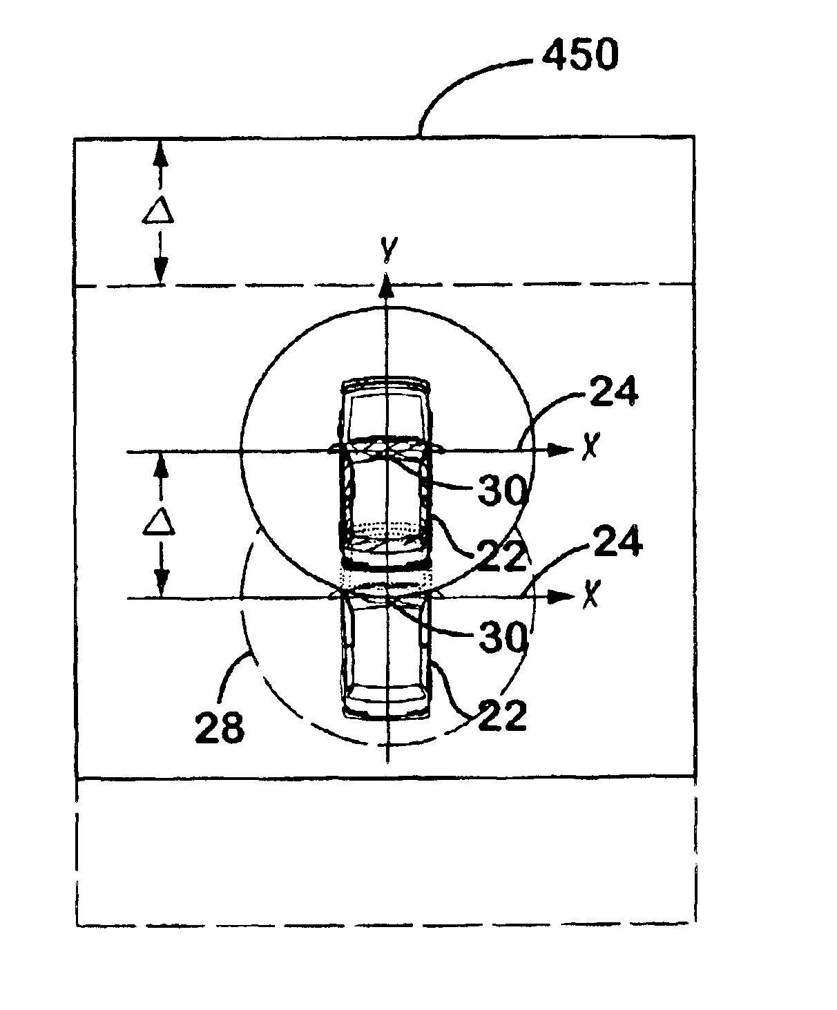
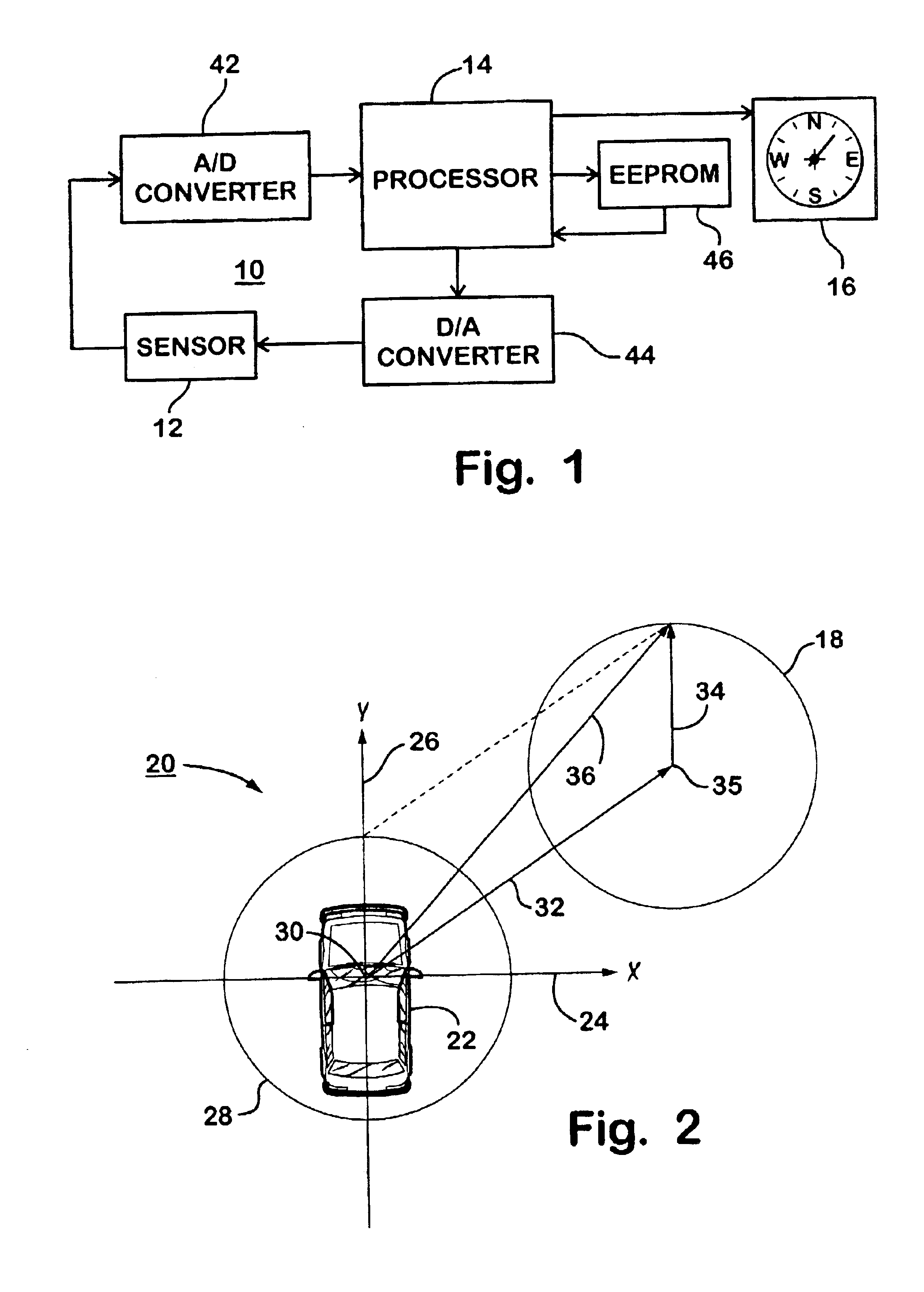
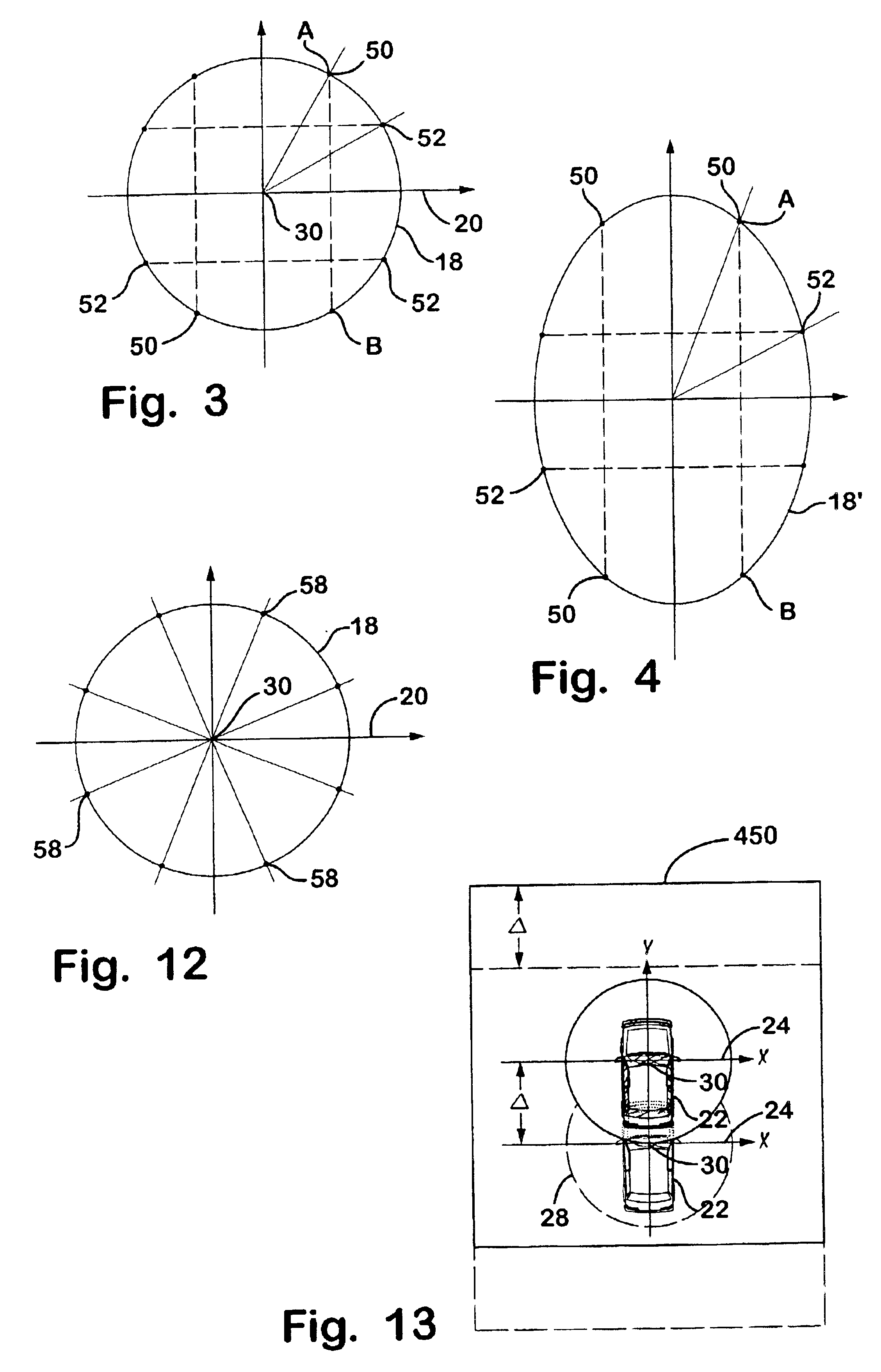
[0030]Referring now to the drawings and the illustrative embodiments depicted therein, there is shown in FIG. 1 a block diagram of an electronic compass system 10 having a calibration system according to the present invention. Electronic compass system 10 may be installed on a vehicle, such as a car, truck, mini-van, light truck, sport utility vehicle, motorcycle, boat, airplane or the like, to provide the operator or passengers of the vehicle with information pertaining to a directional heading of the vehicle. Electronic compass system 10 includes a magneto-responsive sensor 12, such as a magneto-resistive sensor of the type disclosed in commonly assigned U.S. Pat. No. 5,255,442 issued to Schierbeek et al., the disclosure of which is hereby incorporated herein by reference, a magneto-inductive sensor of the type disclosed in commonly assigned U.S. Pat. No. 5,924,212 issued to Domanski, or in U.S. Pat. Nos. 5,239,264 and 4,851,775, the disclosures of which are hereby incorporated he...


PUM


Abstract

A compass compensation system is provided for automatically and continuously calibrating an electronic compass for a vehicle, without requiring an initial manual calibration or preset of the vehicle magnetic signature. The system initially adjusts a two axis sensor of the compass in response to a sampling of at least one initial data point. The system further calibrates the compass by sampling data points that are substantially opposite to one another on a plot of a magnetic field and averaging an ordinate of the data points to determine a respective zero value for the Earth magnetic field. The system also identifies a change in magnetic signature and adjusts the sensor assembly.

Description

CROSS-REFERENCE TO RELATED APPLICATION[0001]This application is a division of U.S. patent application Ser. No. 09 / 540,702, filed on Mar. 31, 2000, now U.S. Pat. 6,513,252, which claims priority from provisional patent application Ser. No. 60 / 128,262, filed on Apr. 8, 1999.BACKGROUND OF THE INVENTION[0002]This invention relates to a calibration system for a magnetic heading sensor, or compass, in a vehicle, and, more particularly to a continuous and fully automatic calibration system for the compass in the vehicle. The invention can be applied to a magneto-inductive sensor, magneto-resistive sensor, flux gate sensor and other known sensing technology.[0003]Many vehicles today are equipped with magnetic compasses to determine the direction in which the vehicle is heading and convey such information to the passengers and / or driver of the particular vehicle. Generally, these magnetic compasses include a magneto-responsive sensor, such as a magnetic rotor sensor, a flux gate sensor, a ma...

Claims


Application Information

Patent Timeline
Patent Type & Authority Patents(United States)
IPC IPC(8): G01C17/38G01C17/00
CPCG01C17/38
Inventor SCHIERBEEK, KENNETH L.HOEKSTRA, ERIC J.BLANK, RODNEY K.VEISEH, MERDADDEVETTE, GREGORY H.SCHOFIELD, KENNETH
Owner DONNELLY CORP
Why Eureka
Try Eureka