Pin locking dual shaft hinge

a dual-shaft hinge and locking technology, applied in the direction of manufacturing tools, instruments, etc., can solve the problems of inconvenient use, and achieve the effect of increasing the applicable field and facilitating the modification or modification of the design

Active Publication Date: 2014-07-15
JARLLYTEC CO LTD
View PDF13 Cites 77 Cited by
  • Summary
  • Abstract
  • Description
  • Claims
  • Application Information

AI Technical Summary

Benefits of technology

[0006]In view of the mentioned disadvantages, one primary objective of the present invention is to provide a pin locking dual shaft hinge, in which the technical means of a first connecting member of a connecting support being formed with a penetrated hole and an insertion pin being formed with cut surfaces is provided for adjusting the whole volume of the present invention, and a cut opening is formed on the first connecting member for being communicated with the penetrated hole, so the flexibility for modifying or altering the design become easier, thereby the present invention being suitably to be applied in a small electronic product so as to increase the applicable fields of the present invention.
[0007]Another objective of the present invention is to provide a pin locking dual shaft hinge capable of reducing foreign noise, thereby functions of lowering the noise caused by collision and prolonging the service life of a rigid wheel member being provided.
[0010]According to the pin locking dual shaft hinge provided by the present invention, the technical means of the first connecting member of the connecting support being formed with the penetrated hole and the insertion pin being formed with cut surfaces is provided for adjusting the whole volume of the present invention, and the cut opening is formed on the first connecting member for being communicated with the penetrated hole, so the flexibility for modifying or altering the design become easier, thereby the present invention being suitably to be applied in a small electronic product so as to increase the applicable fields of the present invention, and the action order of the dual shaft hinge can be ensured and the rotating stability for the electronic device for being folded or unfolded can be kept.

Problems solved by technology

When the pulley disclosed in the patent mentioned in prior art is desired to have its dimension to be adjusted for being reduced or enlarged, because the curvature radius of the wheel body of the pulley is fixed, if only the pulley is adjusted (the dimension being reduced or enlarged), a situation of the contact surface between the adjusted pulley and the concave part of each of the engaging cams being uneasy to be tightly adjacent, thereby affecting the locking effect, and in the process of being moved so as to be mounted, a noise is easily caused because of the collision, and two ends of the pulley are respectively inserted in a slide hole of the first and the second connection sheet by utilizing a convex column, a situation of the first and the second connection sheet being altered with the pulley can be caused, thereby being inconvenience in use.

Method used


Image

  • Pin locking dual shaft hinge
  • Pin locking dual shaft hinge
  • Pin locking dual shaft hinge

Examples


first embodiment

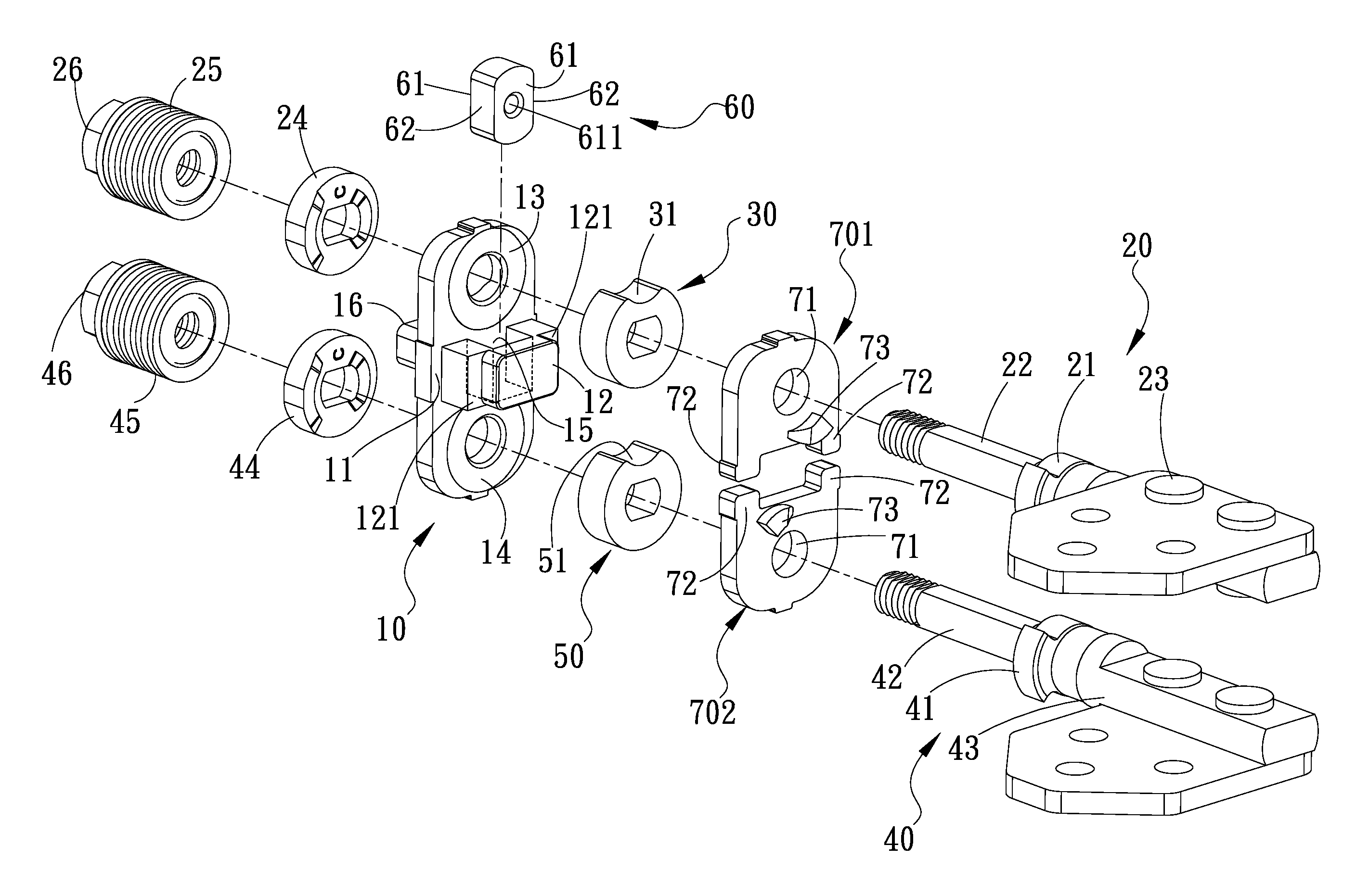
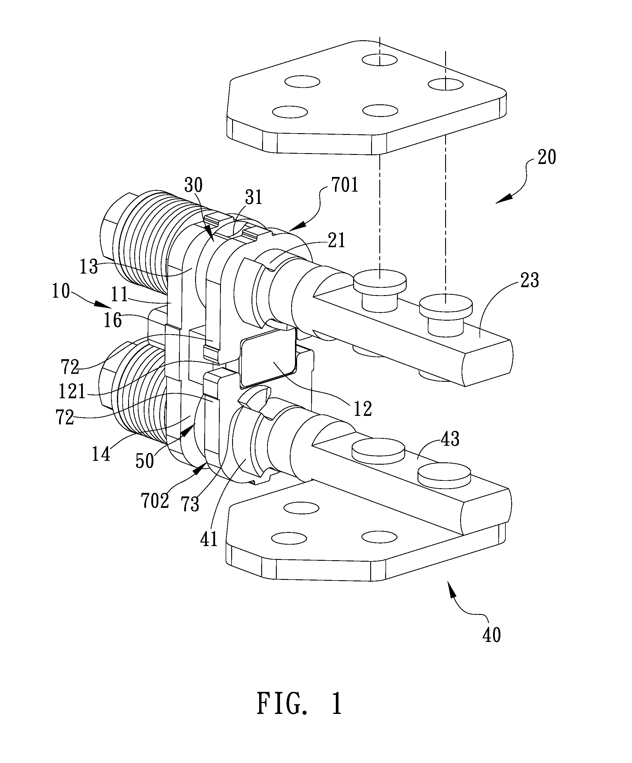
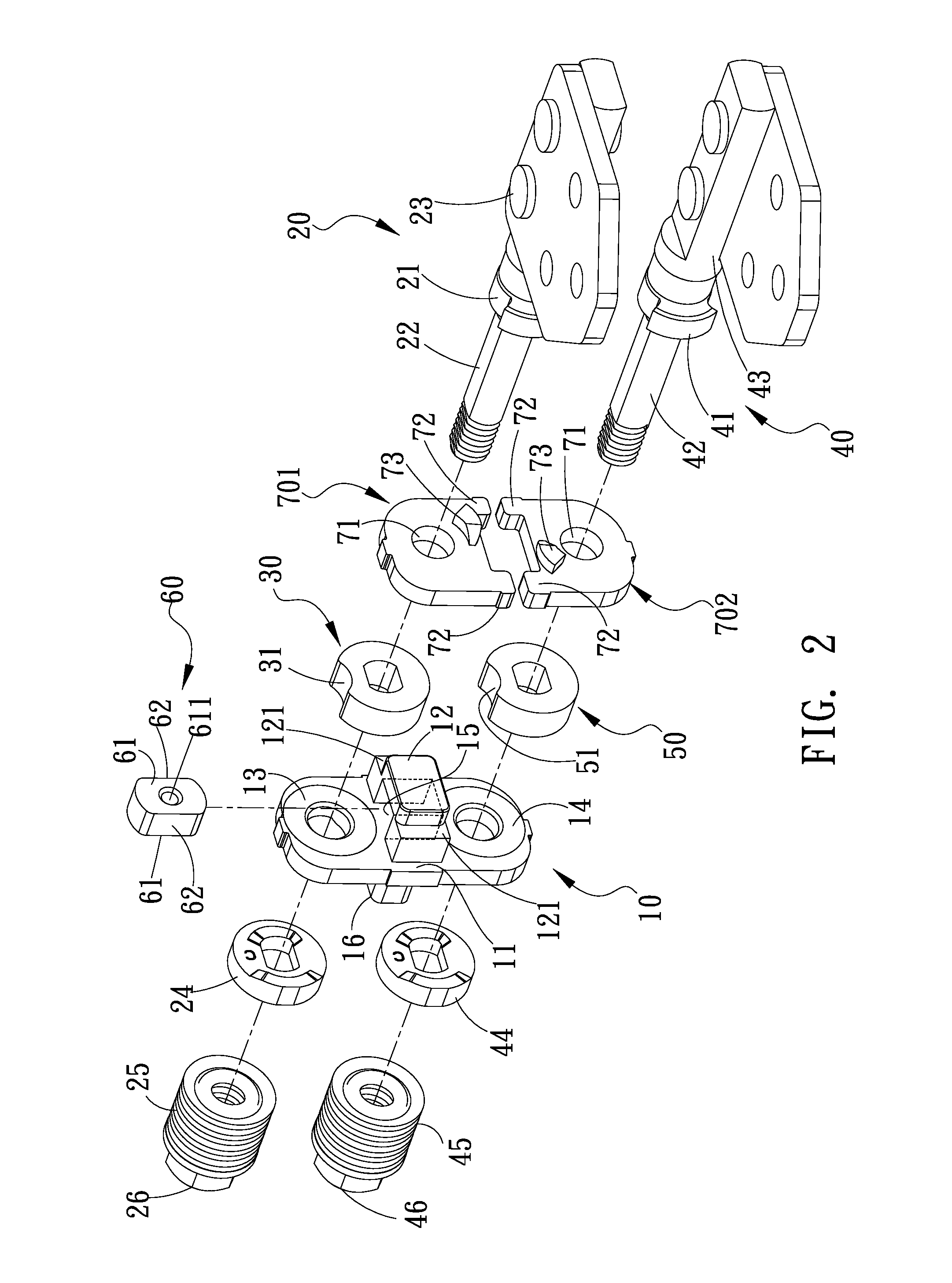
[0022]Referring from FIG. 1 to FIG. 7, according to the present invention, the pin locking dual shaft hinge includes a connecting support 10, a first core shaft 20, a first engaging cam 30, a second core shaft 40 parallel to the first core shaft 20, a second engaging cam 50 and an insertion pin 60.

[0023]The connecting support 10 includes a main body 11 and a first connecting member 12, the first connecting member 12 is formed on a wall surface of the main body 11 and between an upper end 13 and a lower end 14 of the main body 11, the connecting support 10 is formed with a penetrated hole 15 penetrating the first connecting member 12. The first core shaft 20 is pivoted at the upper end 13 of the main body 11. The first engaging cam 30 is sleeved and engaged on the first core shaft 20 and disposed close to the upper opened portion of the penetrated hole 15, the periphery of the first engaging cam 30 is formed with at least a first engaging part 31. The second core shaft 40 is pivoted ...

second embodiment

[0033] a main function of reducing the whole volume is provided, because the another cut surface 61 of the insertion pin 60 is corresponding to the cut opening 122 of the first connecting member 12, when in actual practice, an engaging status or a releasing status can be formed between the another cut surface 61 and the position limiting fasten sheet 703 through adjusting the dimension of the cut opening 122 so as to reduce or increase the whole volume of the present invention. Accordingly, the pin locking dual shaft hinge provided by the present invention is able to be applied in various electronic products.


PUM


Abstract

The present invention relates to a pin locking dual shaft hinge, including a connecting support, a first core shaft and a second core shaft parallel to each other, a first engaging cam, a second engaging cam and an insertion pin. The connecting support includes a main body and a first connecting member disposed between an upper and a lower end thereof, the first connecting member is penetrated with a penetrated hole. The first core shaft and the second core shaft are respectively pivoted at the upper and lower end of the main body. The first engaging cam is sleeved and engaged on the first core shaft, the periphery of the first engaging cam is formed with at least a first engaging part. The second engaging cam is sleeved and engaged on the second core shaft, the periphery of second engaging cam is formed with at least a second engaging part.

Description

BACKGROUND OF THE INVENTION[0001]1. Field of the Invention[0002]The present invention relates to a pin locking dual shaft hinge, especially to a hinge having dual shafts and capable of being rotated in 360 degrees and being applicable in a cover-lifting electronic device.[0003]2. Description of Related Art[0004]For allowing a general cover-lifting electronic product (e.g. a notebook computer, a mobile phone or an electrical book reader) to have its screen to be opened and rotated over 180 degrees (e.g. rotated to 360 degrees) relative to a main body thereof (the main body being installed with a keyboard) without generating interfere, a dual shaft hinge is therefore developed, take the Taiwan Patent No. M438797 granted to the applicant of the present invention for instance, the pulley pin locking dual shaft hinge includes a first rotation shaft, a second rotation shaft, a first connection sheet and a second connection sheet, the first rotation shaft is installed with a first engaging...

Claims


Application Information

Patent Timeline
Patent Type & Authority Patents(United States)
IPC IPC(8): E05D11/08F16H19/08E05D7/00
CPCY10T16/5387Y10T16/54038E05Y2900/606Y10T16/547Y10T16/540255E05D7/00G06F1/16F16H19/08G06F1/1681
Inventor CHANG, JUI-HUNGLIAO, KUO-TUNG
Owner JARLLYTEC CO LTD
Why Eureka
Try Eureka