
Two-stage dual-pintle hinge

Inactive Publication Date: 2011-11-03
SINHER TECH INC
View PDF3 Cites 79 Cited by
  • Summary
  • Abstract
  • Description
  • Claims
  • Application Information

AI Technical Summary

Benefits of technology

[0005]Therefore, the primary object of the present invention is to provide a dual-pintle hinge that can be pivoted at two stages in a sequence and provide a longer lifespan.
[0007]By means of the structure set forth above, only the first stage pivot displacement between the first axis and connecting element has been finished, the second stage pivot displacement between the connecting element and second axis can be driven, so that pivot displacements are performed in a constant sequence. Moreover, both the first and second axes can form anchoring effect with the connecting element to provide auxiliary support and increase the life span.

Problems solved by technology

While it allows the display to be lifted and pivoted against the keyboard, it has only one axis and the axis cannot be altered during swiveling.
However, the successive movements of the two single-pintle hinges of the aforesaid dual-pintle hinge cannot be controlled as desired.
As a result, the flipping condition is unpredictable to the user.
Moreover, anchoring effect of the frames is merely relied on the rotary cam and fixed cam, the cam surfaces have to support the weight of the frames for a long time and be worn off quickly, thus result in a shorter lifespan.

Method used


Image

  • Two-stage dual-pintle hinge
  • Two-stage dual-pintle hinge
  • Two-stage dual-pintle hinge

Examples


Embodiment Construction

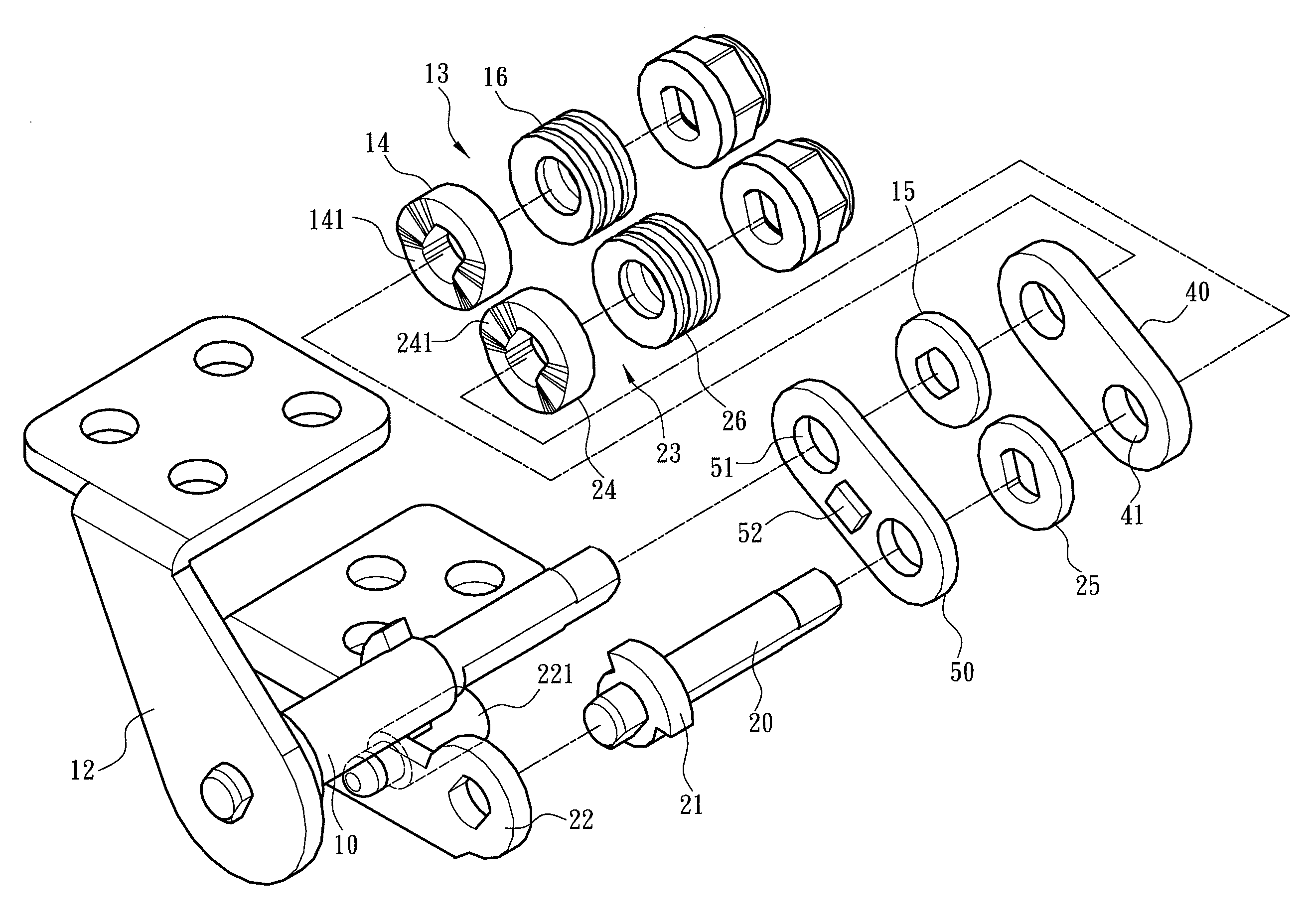
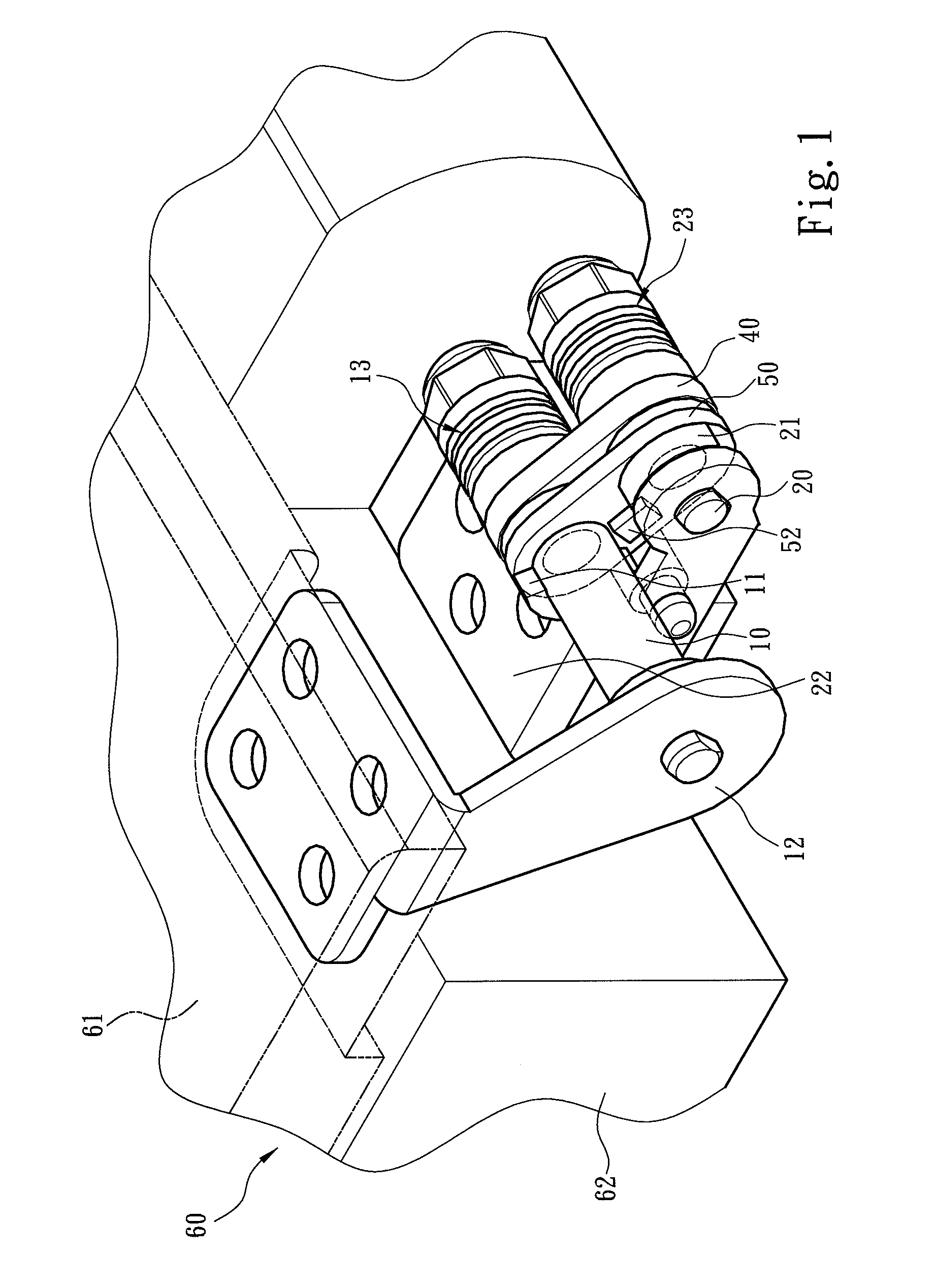
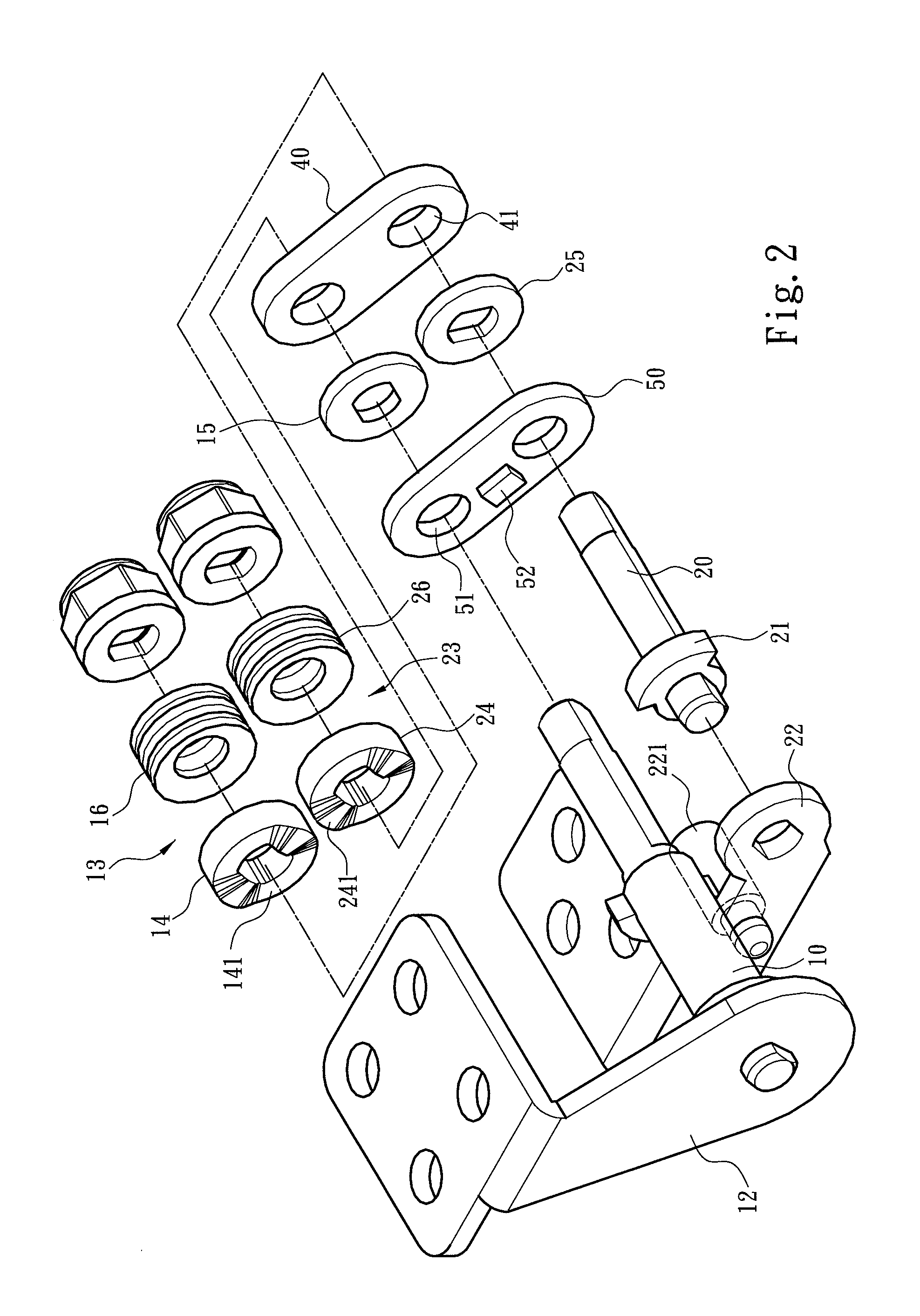
[0013]Please refer to FIGS. 1, 2 and 3, the present invention aims to provide a two-stage dual-pintle hinge which mainly includes a first axis 10, a second axis 20 and at least one connecting element to connect the first and second axes 10 and 20. The first axis 10 is connected to a first mounting plate 12 and has a first torsion unit 13 and a first anchor portion 11. The second axis 20 is connected to a second mounting plate 22 and has a second torsion unit 23 and a second anchor portion 21. The first and second torsion units 13 and 23 include respectively a cam 14 and 24, a friction pad 15 and 25, and an elastic pad 16 and 26 run through respectively by the first and second axes 10 and 20.

[0014]Refer to the drawings for an embodiment of the invention in which a first connecting element 40 and a second connecting element 50 are provided that have respectively two apertures 41 and 51 run through by the first and second axes 10 and 20 in the same direction. The first axis 10 and the ...


PUM


Abstract

A two-stage dual-pintle hinge mainly includes at least one connecting element which has two apertures run through by a first axis and a second axis in the same direction. The first axis and the connecting element form a first pivot displacement, and the second axis and the connecting element form a second pivot displacement. The first and second axes have respectively a first anchor portion and a second anchor portion. The connecting element has a corresponding third anchor portion. During the first pivot displacement, the first anchor portion and the third anchor portion form an anchor relationship and drive the second pivot displacement of the connecting element and the second axis. During the second pivot displacement, the second anchor portion and the third anchor portion form an anchor relationship to stop pivoting.

Description

FIELD OF THE INVENTION[0001]The present invention relates to a two-stage dual-pintle hinge and particularly to a dual-pintle hinge equipped with two single-pintle hinges that can be pivoted in a two-stage manner.BACKGROUND OF THE INVENTION[0002]The conventional flip-lid electronic device (such as notebook computer, mobile phone and the like) generally has a hinge to bridge a display and a keyboard, and provide a torsional force required for lifting the display against the keyboard. The conventional hinge generally has a single-pintle. While it allows the display to be lifted and pivoted against the keyboard, it has only one axis and the axis cannot be altered during swiveling.[0003]To remedy the aforesaid problem, a “dual-pintle” hinge has been developed as disclosed in PCT patent No. WO 2007 / 029546. It proposes a dual-pintle hinge to bridge two frames of an electronic device, and mainly includes a rotary cam run through by two switch shafts. The switch shaft has a fixed cam and a s...

Claims


Application Information

Patent Timeline
IPC IPC(8): E05D11/08E05D3/06
CPCE05D3/12E05D11/087G06F1/1681Y10T16/547Y10T16/5478Y10T16/5403Y10T16/54035E05Y2900/606E05Y2999/00
Inventor CHIANG, YUNG-CHANG
Owner SINHER TECH INC
Learn More