
Electronics device having projector module

a technology of electronic devices and projectors, which is applied in the field of electronic devices, can solve the problems of damage to hands, difficulty in operating the operating portion of such an electronic device without moving the device itself, and difficulty in watching a projected imag

Active Publication Date: 2009-10-22
RICOH KK
View PDF11 Cites 85 Cited by
  • Summary
  • Abstract
  • Description
  • Claims
  • Application Information

AI Technical Summary

Benefits of technology

[0032]Various other objects, features and attendant advantages of the present invention will be more fully appreciated as the same becomes better understood from the detailed description when considered in connection with the accompanying drawings in which like reference characters designate like corresponding parts throughout and wherein:
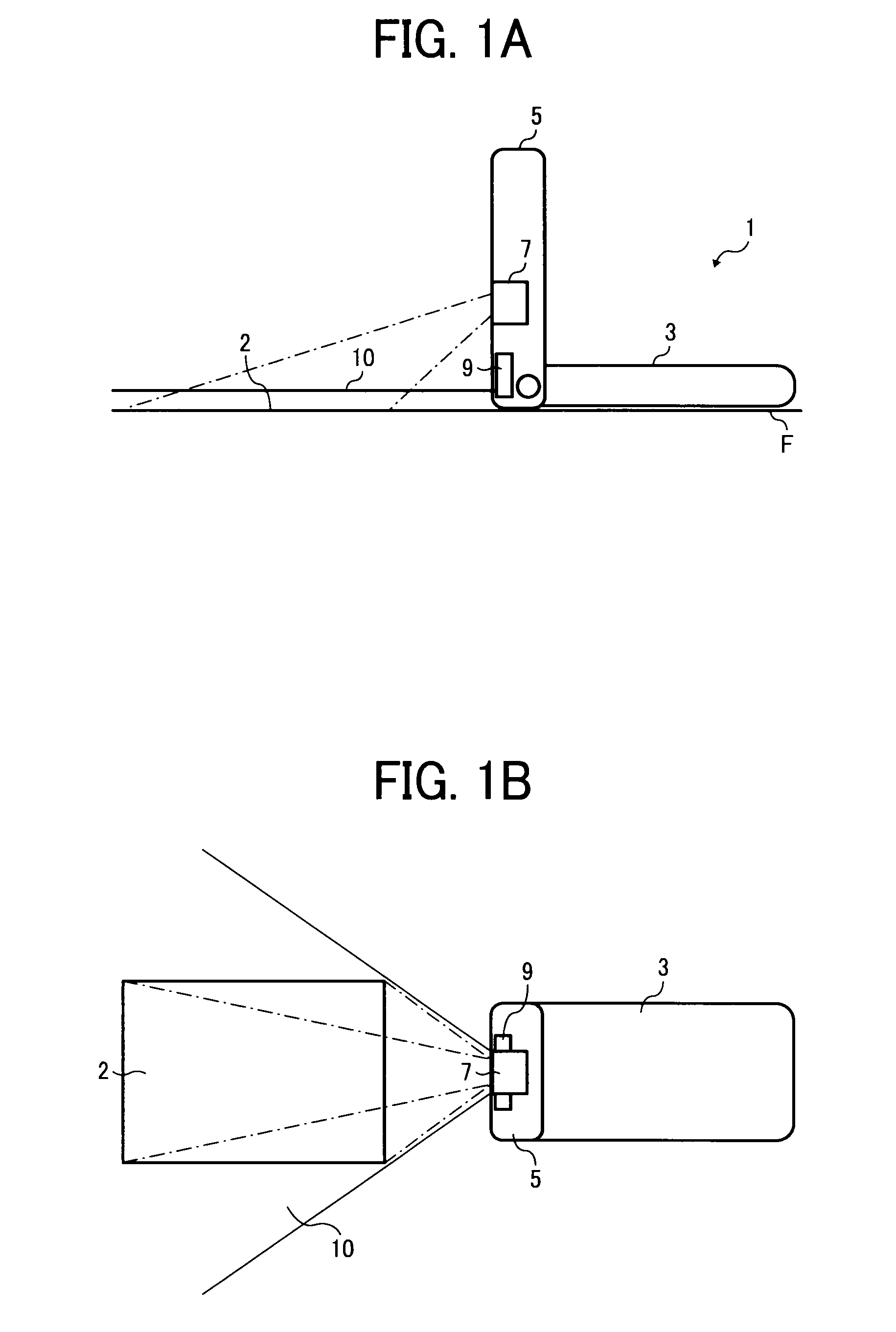
[0033]FIGS. 1A and 1B are views illustrating an example (mobile phone) of the electronics device of the present invention, which projects an image on a desk;
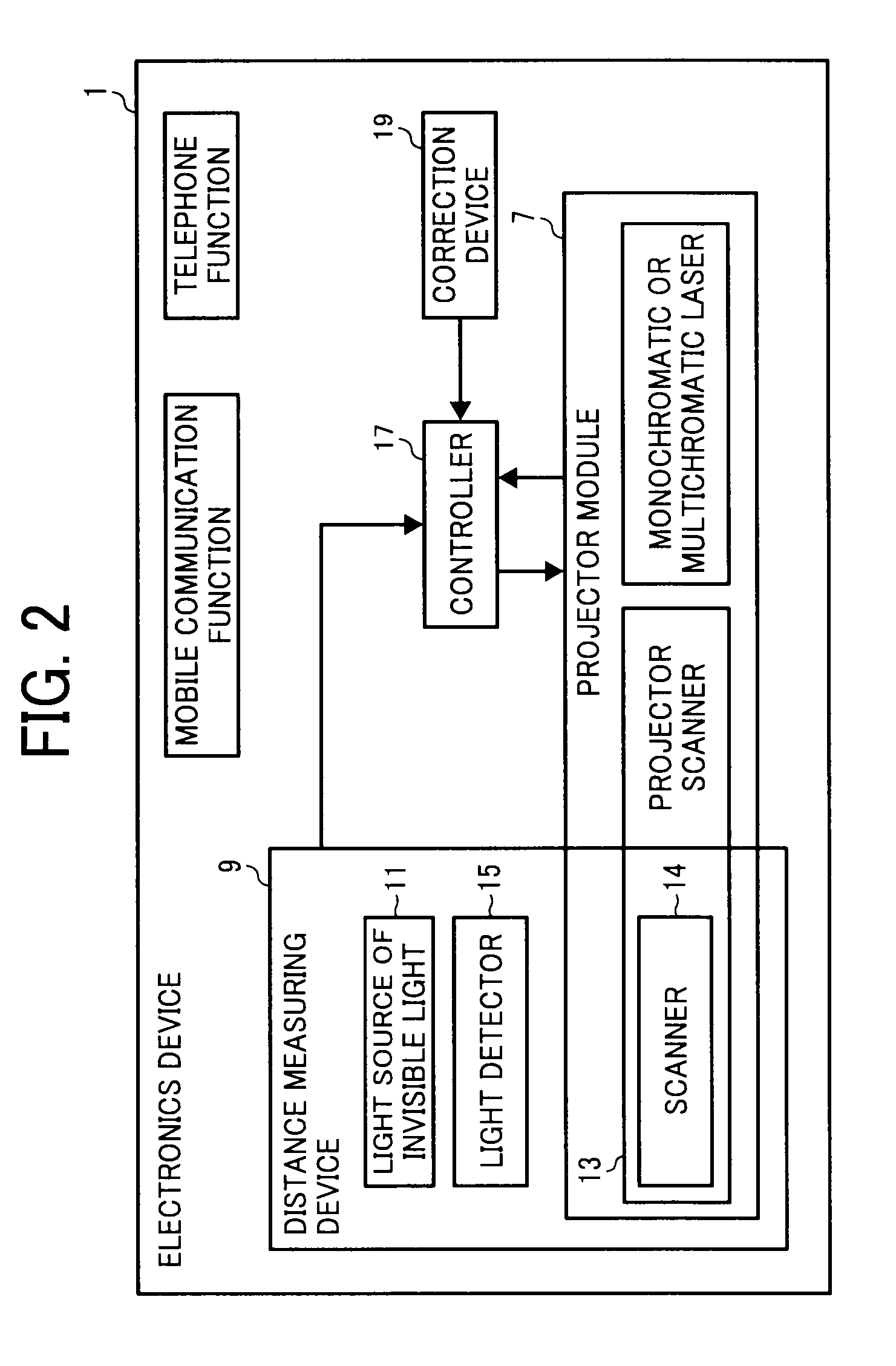
[0034]FIG. 2 is a block diagram of the electronics device illustrated in FIG. 1;
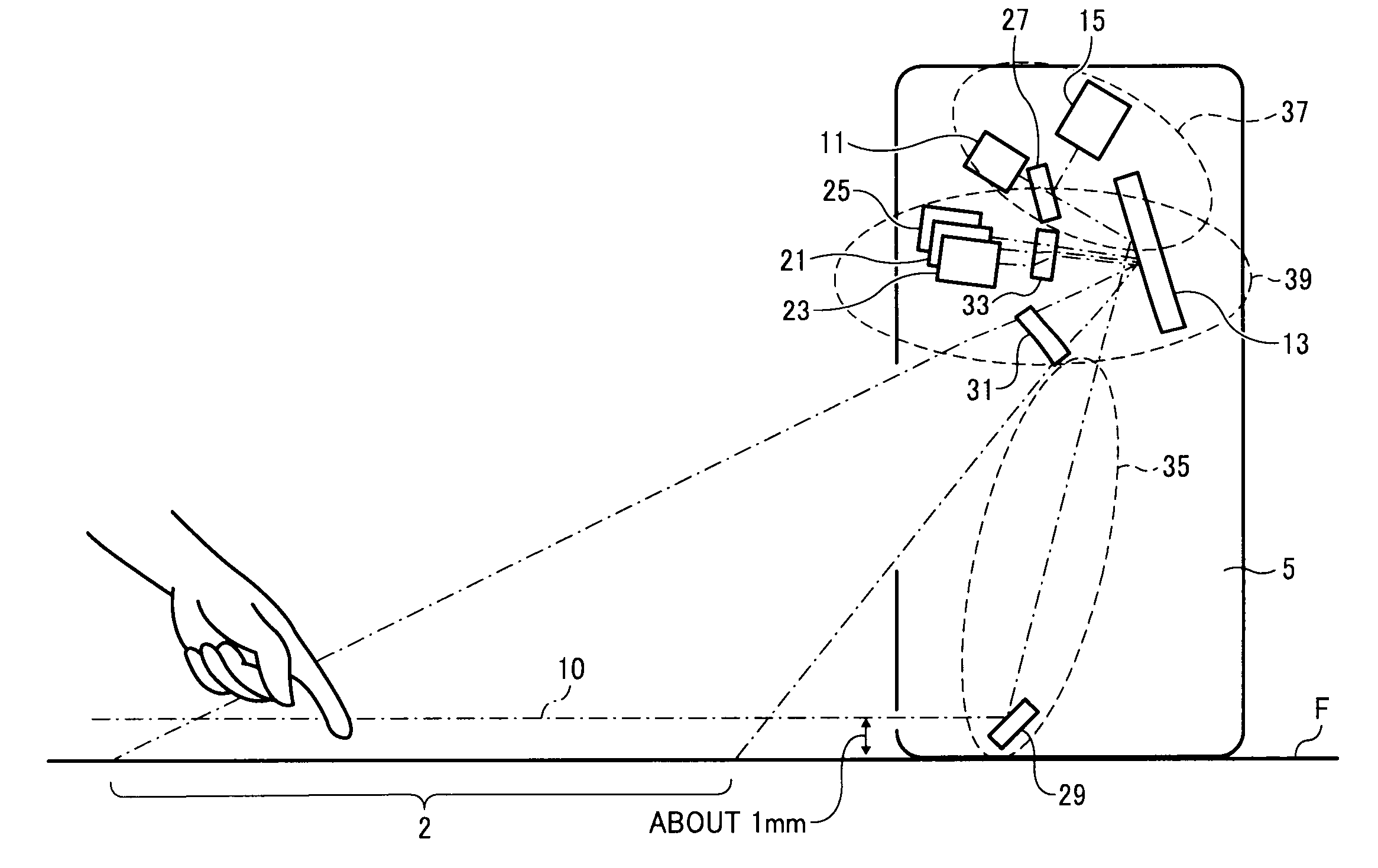
[0035]FIG. 3 is a cross sectional view of the electronics device;
[0036]FIG. 4 illustrates a MEMS mirror serving as a projector scanner of the electronics device;
[0037]FIG. 5 is a view for explaining that the MEMS mirror also serves as a scanner (second scanner) of a distance measuring device of the electronics device;
[0038]FIG. 6 is a plan view of the electronics device for explaining how the distance measuring device performs scanning;
[0039]FIG. 7 is a view for explaining a Time of Flight (TOF) method used for the distance measuring device;
[0040]FIG. 8 is a view for explaining advantages of the electronics device in detecting a finger serving as an optical interceptor;
[0041]FIG. 9 is a block diagram illustrating the controlling operation of a controller of the electronics device;
[0042]FIGS. 10A and 10B are views for explaining whether or not touching is performed by an optical interceptor;
[0043]FIGS. 11 and 12 are flowcharts for explaining examples of the correction operation of the electronics device;
[0044]FIGS. 13A and 13B are views illustrating another example of the electronics device of the present invention;
[0045]FIG. 14 is a view illustrating yet another example of the electronics device of the present invention;
[0046]FIG. 15 is a block diagram of the electronics device illustrated in FIG. 14;
[0047]FIG. 16 is a longitudinal section illustrating a camera module of the electronics device illustrated in FIG. 14;
[0048]FIG. 17 is a perspective view illustrating a mobile phone projecting an image on a desk; and
[0049]FIG. 18 is a view for explaining a touching operation on a virtual keyboard of a background electronics device.

Problems solved by technology

In this case, there are problems to be solved such that the image is blurred due to hand movement, and the hand is damaged by heat generated by the phone.
Specifically, it is difficult to operate the operating portion of such an electronics device without moving the device itself.
If the device is moved by an operation, the image is also moved during the operation and therefore it is difficult to watch a projected image.
Thus, it is inconvenient to perform an image projection operation using the electronics device itself.
It is considered to use a remote controller for such an image projection operation, but an electronics device in combination with a remote controller is inferior in mobility and cost.
Therefore, appearance of the electronics devices (such as mobile phones) is not good.
Therefore, the image processing device has high costs.
The laser projection display seems to have a low accuracy in detecting the height of a finger, namely the accuracy in determining whether a key of a virtual keyboard is pushed is low.
Therefore, detection errors may often occur.
The accuracy in measuring a distance by this method is insufficient for determining the height of a foot (determining the height of a foot is a severe distance measuring operation).
Thus, the technique has low detection accuracy.

Method used


Image

  • Electronics device having projector module
  • Electronics device having projector module
  • Electronics device having projector module

Examples


Embodiment Construction

[0050]The present invention relates to an electronics device having a projector module projecting an image on a projection surface such as desktop. Specific examples of the electronics device include projectors themselves, mobile phones, notebook computers, personal digital assistants (PDAs), game machines, digital cameras, etc. The present invention is preferably used for mobile electronics devices, but is not limited thereto.

[0051]A first example of the electronics device of the present invention will be explained by reference to FIGS. 1 to 12.

[0052]FIGS. 1A and 1B schematically illustrate the layout of a mobile phone according to an example of the present invention, and FIG. 2 is the block diagram of the mobile phone.

[0053]Referring to FIGS. 1A and 1B, a mobile phone 1 is a flip phone having a lower portion 3 having a telephone function and including operational keys, and an upper portion 5 including a display. As illustrated in FIGS. 1A and 1B, the mobile phone 1 is used in such...


PUM


Abstract

An electronics device having a projector module including a first light source, and a first scanner scanning an image projection surface in a biaxial direction; a distance measuring device performing one-dimensional scanning on a plane over the image projection surface to determine the position of an optical interceptor and including a second light source, a second scanner performing scanning with the second light beam, and a light detector detecting the second light beam reflected from the optical interceptor; and a controller. The uniaxial-scanning component of the first scanner is shared with the second scanner. The positional data are compared with two-dimensional coordinate data of the projected image to determine the position of the optical interceptor on the projected image. The controller inputs a signal to the electronics device when determining that the optical interceptor performs optical interception on the projected image.

Description

BACKGROUND OF THE INVENTION[0001]1. Field of the Invention[0002]The present invention relates to an electronic device having a projector module. Particularly, the present invention relates to an electronics device having a projector module capable of performing desktop projection.[0003]2. Discussion of the Background[0004]Use of projectors as tools for home theaters and meetings using personal computers is rapidly spreading. Recently, small portable projectors to be used in combination with notebook computers have been developed. Such portable projectors are preferably used for meetings (such as presentations) held at a room having no projector.[0005]Under such circumstances, there are movements such that a projector is incorporated in electronics device such as mobile phones. By incorporating a projector into such mobile electronics devices, the convenience of the devices can be dramatically enhanced.[0006]Such mobile electronics devices having a projector are considered to be used...

Claims


Application Information

Patent Timeline
IPC IPC(8): G06F3/042
CPCG06F1/1616G06F1/1639G06F1/1673G06F1/169H04N9/3141G06F3/0423G06F3/04886H04N5/7416G06F3/0418
Inventor YAMADA, MASAFUMI
Owner RICOH KK
Learn More