Multiple dwelling house

a multi-dwelling house and multi-family technology, applied in special buildings, parkings, buildings types, etc., to achieve the effect of wide space, effective ceiling height dimension, and increased ceiling height dimension

Inactive Publication Date: 2005-08-02
INST OF INT ENVIRONMENT +1
View PDF8 Cites 41 Cited by
  • Summary
  • Abstract
  • Description
  • Claims
  • Application Information

AI Technical Summary

Benefits of technology

[0010]In addition, since each intermediate slab disposed between adjacent upper and lower floors is a flat slab, a dwelling-unit space positioned below the slab is lower in ceiling height dimension than a dwelling-unit space positioned above the slab. However, a structural floor height (defined herein as the distance between the upper surfaces of adjacent upper and lower beams) can be ensured by a predetermined amount, and each of a ceiling face and a floor face becomes a flat face so that a space defined between upper and lower faces having no unevenness can be obtained and hence a wide space can be obtained, whereby it is possible to ensure an effective ceiling height dimension.
[0011]On the other hand, in the dwelling-unit space positioned above the slab, its floor face is positioned below its flat slab, whereby it is possible to realize a dwelling-unit space having a large ceiling height dimension by forming the face of the flat slab as a finished floor face.
[0012]As described above, it is possible to increase the ceiling height dimension of either of the upper and lower floors, whereby it is possible to form a rich three-dimensional space marked by variety.

Problems solved by technology

Accordingly, there has not yet been an idea which aims to positively realize a multiple dwelling house securing a ceiling height effectively while having different ceiling heights capable of meeting a variety of needs of users.
Furthermore, during the construction of a building, the flat slab method is applied to only predetermined floors or to the entire multiple dwelling house.

Method used


Image

  • Multiple dwelling house
  • Multiple dwelling house
  • Multiple dwelling house

Examples


first embodiment

[0032]the invention will be described below.

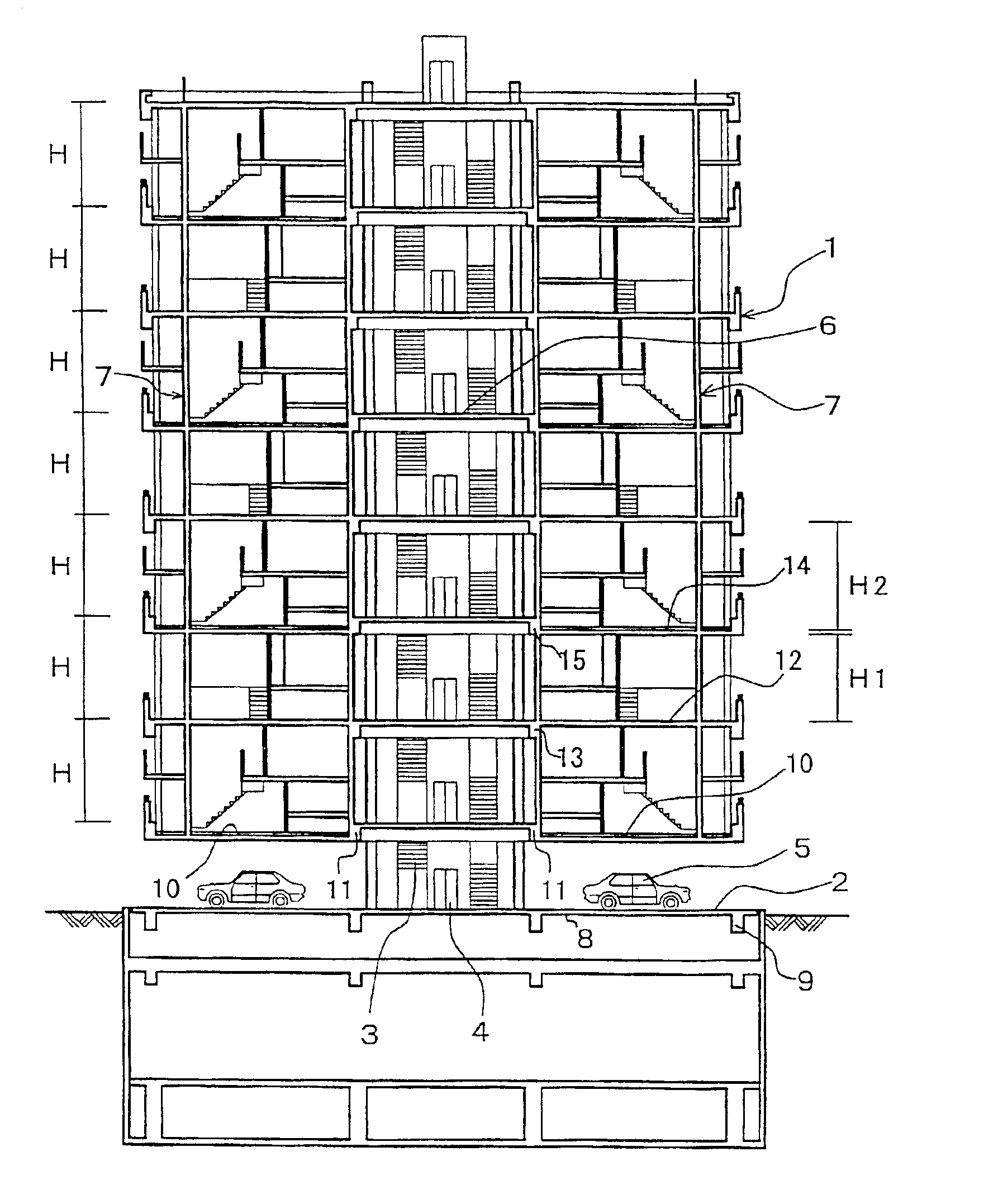
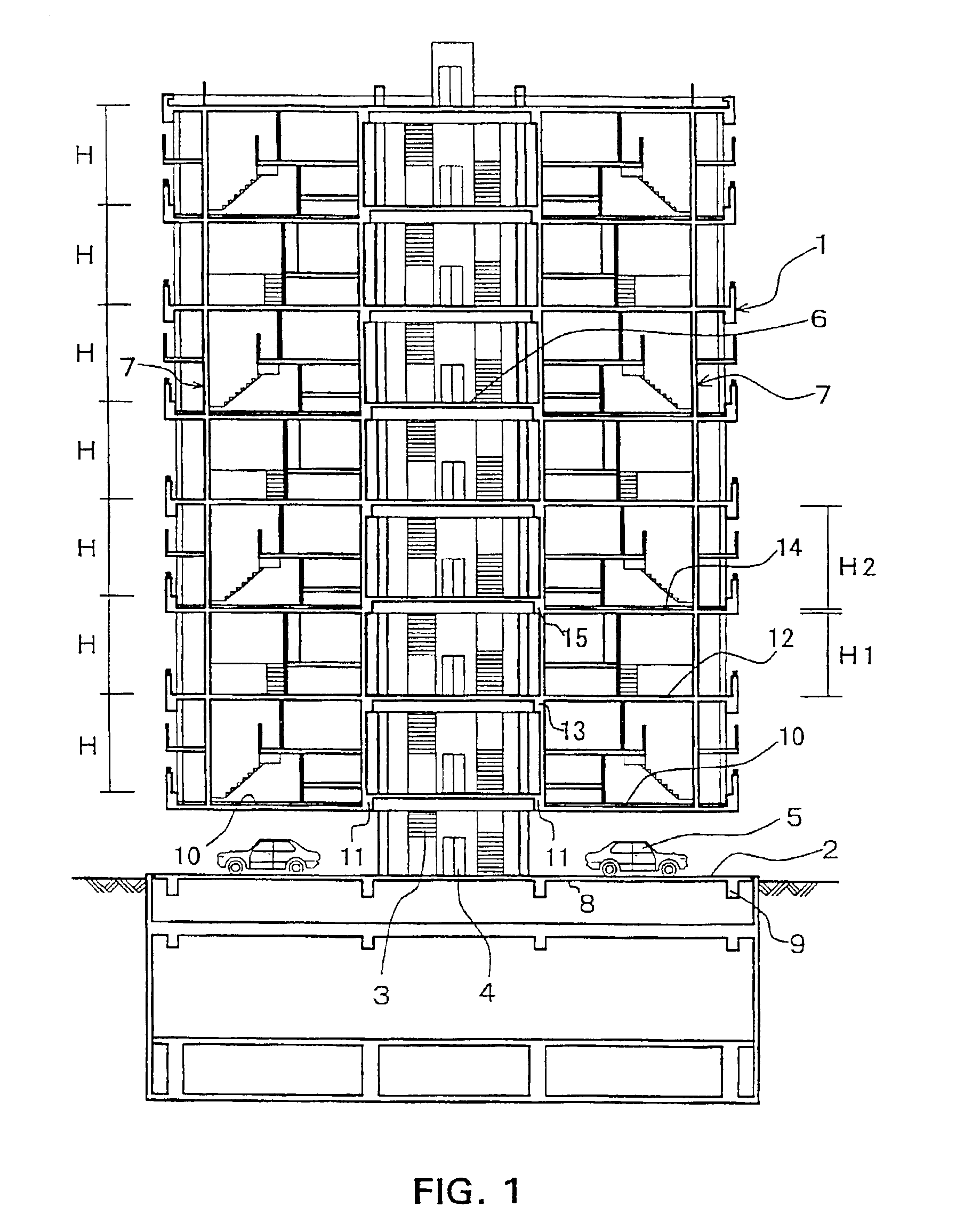
[0033]FIG. 1 is a cross-sectional view showing a medium-rise multiple dwelling house.

[0034]The multiple dwelling house according to the first embodiment is a multiple dwelling house 1 having eight floors above ground level and one floor below ground level. The first floors above and below ground level have an entrance hall, a parking area and a space associated therewith, and standard floors which include the second to eighth floors have dwelling units.

[0035]The parking area on the first floor below ground level includes a mechanical two-storied car parking system, and the first floor above ground level includes an entrance hall 2 which is an approach to the upper floors, stairs 3, an elevator 4, a turntable space for the parking area on the first floor below ground level, and a parking area 5.

[0036]Each of the standard floors includes the stairs 3, the elevator 4 and a common space 6 which includes a hall disposed in front of the elevator...

second embodiment

[0063]the invention will be described below.

[0064]FIG. 6 is a cross-sectional view showing the cross-sectional planning of the second embodiment, and a structural floor height I between the upper beam surfaces of each of the standard floors and those of the next adjacent one is made the same floor height dimension of 3,600 mm.

[0065]The second embodiment will be described below with reference to one unit on each of the second and third floors.

[0066]Similarly to the case of the first embodiment, floor planning is performed on a pair of odd- and even-numbered floors.

[0067]The floor face of the second floor is constructed as a T-beam slab surface, and if the beam depth dimension of each of the beams is made 800 mm, a slab-to-slab dimension I1 of the second floor becomes 2,800 mm. Accordingly, even if the finished thickness dimension of the floor face is taken into account, the ceiling height of each of a living room and a dining kitchen on a reference side which is a living space become...

third embodiment

[0071]the invention will be described below.

[0072]As shown in the cross-sectional view of FIG. 6 referred to above, an upper floor and a lower floor, i.e., a dwelling space having two stories and a dwelling space having a sufficient ceiling height, are planned as one unit. However, the space on either one of the upper and lower floors can also be planned as a common space J.

[0073]The common space J can be constructed as an exterior space such as various kinds of gardens or athletic facilities or an interior space such as various kinds of assembly spaces or indoor athletic facilities, as required.

[0074]The common space J can also be constructed as an exclusive space for a particular resident.

[0075]Furthermore, the common space J can be constructed as a wellhole-style space through which a wind W can blow, whereby the building can be given the function of reducing wind pressure applied to itself or preventing building wind from blowing toward neighboring houses.

[0076]In addition, resi...


PUM


Abstract

The invention provides a multiple dwelling house in which although its standard floors are constructed to have the same structural floor height, the ceiling heights of individual dwelling units positioned above and below each flat slab can be set to differ from each other so that the multiple dwelling house has ceiling heights capable of meeting a variety of needs of users. The multiple dwelling house includes standard floors constructed to have the same structural floor height dimension, intermediate slabs each of which is made of a flat slab and is disposed between each of adjacent upper and lower floors, and slabs each of which is made of a beam slab and forms a ceiling face of the upper floor and a floor face of the lower floor. One unit made of the adjacent upper and lower floors is constructed in a sequentially repeated manner to make dwelling-unit spaces different in ceiling height between the adjacent upper and lower floors.

Description

BACKGROUND OF THE INVENTION[0001]1. Field of the Invention[0002]The present invention generally relates to comparatively low-rise buildings as well as medium- or high-rise buildings, and more particularly, to a multiple dwelling house in which its standard floors have the same structural floor height, wherein individual dwelling-unit spaces constructed on its respective standard floors are set to differ in structural ceiling height between adjacent upper and lower floors so as to meet a variety of needs of users.[0003]2. Background Art[0004]Related-art buildings such as multiple dwelling houses, office buildings or buildings used for both dwelling and office purposes (these houses and building will be hereinafter referred to generally as multiple dwelling houses) include standard floors each having the same slab-to-slab dimension. Accordingly, each of the dwelling units of such a multiple dwelling house has the same dimensions, and the ceiling height of each of the dwelling units is...

Claims


Application Information

Patent Timeline
Patent Type & Authority Patents(United States)
IPC IPC(8): E04H1/04
CPCE04H1/04
Inventor SATAKA, KEIZO
Owner INST OF INT ENVIRONMENT
Why Eureka
Try Eureka