Dual-stage blowhead assembly

a blowhead and assembly technology, applied in glass blowing equipment, glass making equipment, manufacturing tools, etc., can solve the problems of the ratio of final blowing air to finish cooling air, and the possibility of varying the ratio of finish cooling air to final

Inactive Publication Date: 2005-08-02
OWENS-BROCKWAY GLASS CONTAINER INC
View PDF26 Cites 9 Cited by
  • Summary
  • Abstract
  • Description
  • Claims
  • Application Information

AI Technical Summary

Benefits of technology

[0005]A blowhead assembly in accordance with a second aspect of the present invention, for receipt over a parison finish in a glassware forming mold to blow the parison within the mold, includes a blowhead body having a passage for receiving blow air and a tube extending from the passage for receipt within the parison finish. The tube has open ends for directing blow air into the parison and radial passages for directing air against the internal surface of the parison finish. These radial passages preferably are disposed and angled to direct blow air against the finish where the finish abuts the opposing surface of the blowhead to help heal any plunger scar and prevent formation of a wire edge around the inside diameter of the finish mouth. This second aspect of the invention may be implemented in dual-stage blowheads in combination with the first aspect of the invention, or may be implemented in other types of blowheads.

Problems solved by technology

Blowheads of this character have the drawback that the ratio of final-blow air to finish cooling air is determined by the ratio of the diameters of the air passages in the blowhead, as well as other fixed factors.
Since the finish cooling air passages branch from the final-blow air passage within the blowhead, it is not possible to vary the ratio of the finish cooling air to the final blow air.

Method used


Image

  • Dual-stage blowhead assembly
  • Dual-stage blowhead assembly
  • Dual-stage blowhead assembly

Examples


Embodiment Construction

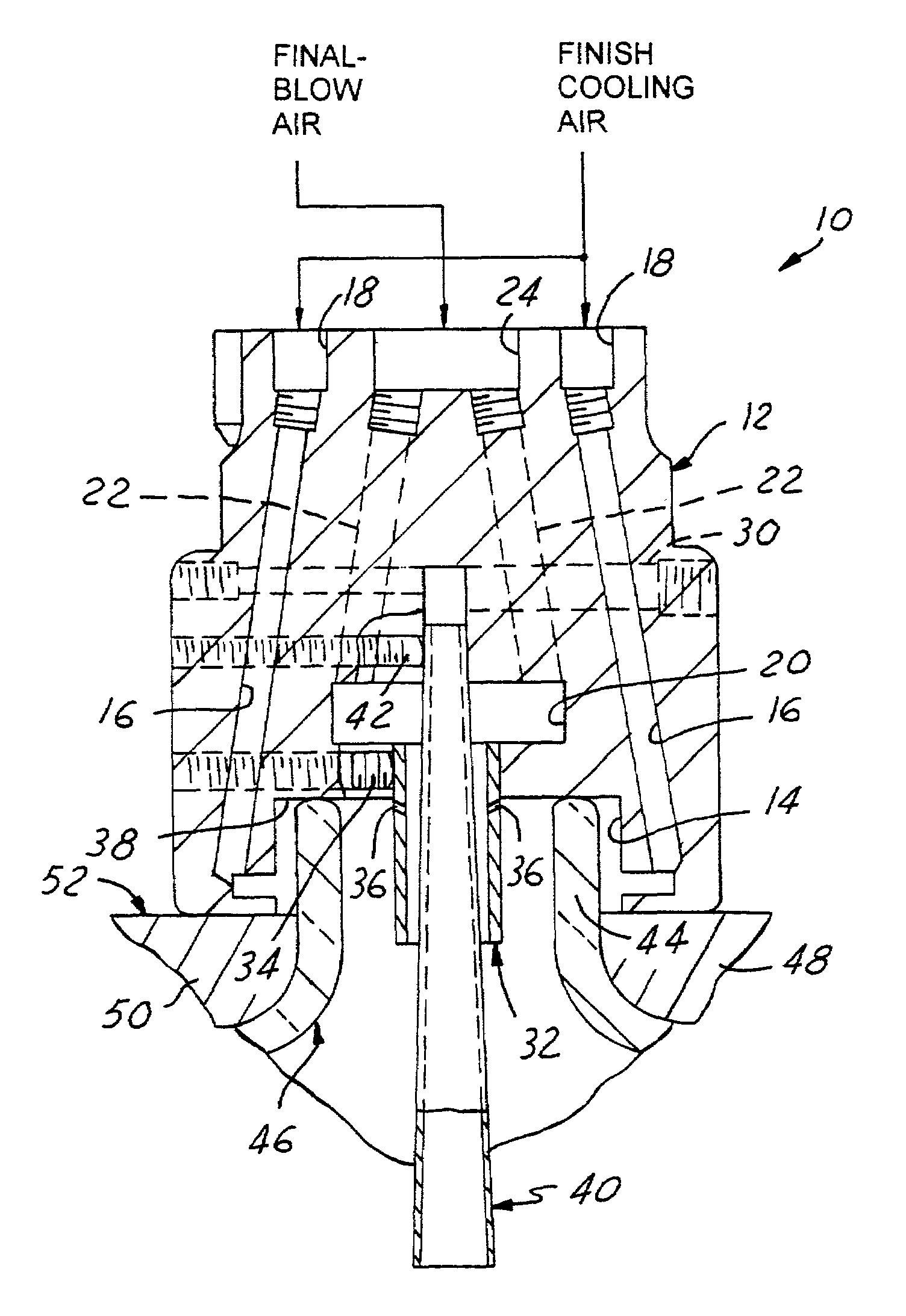
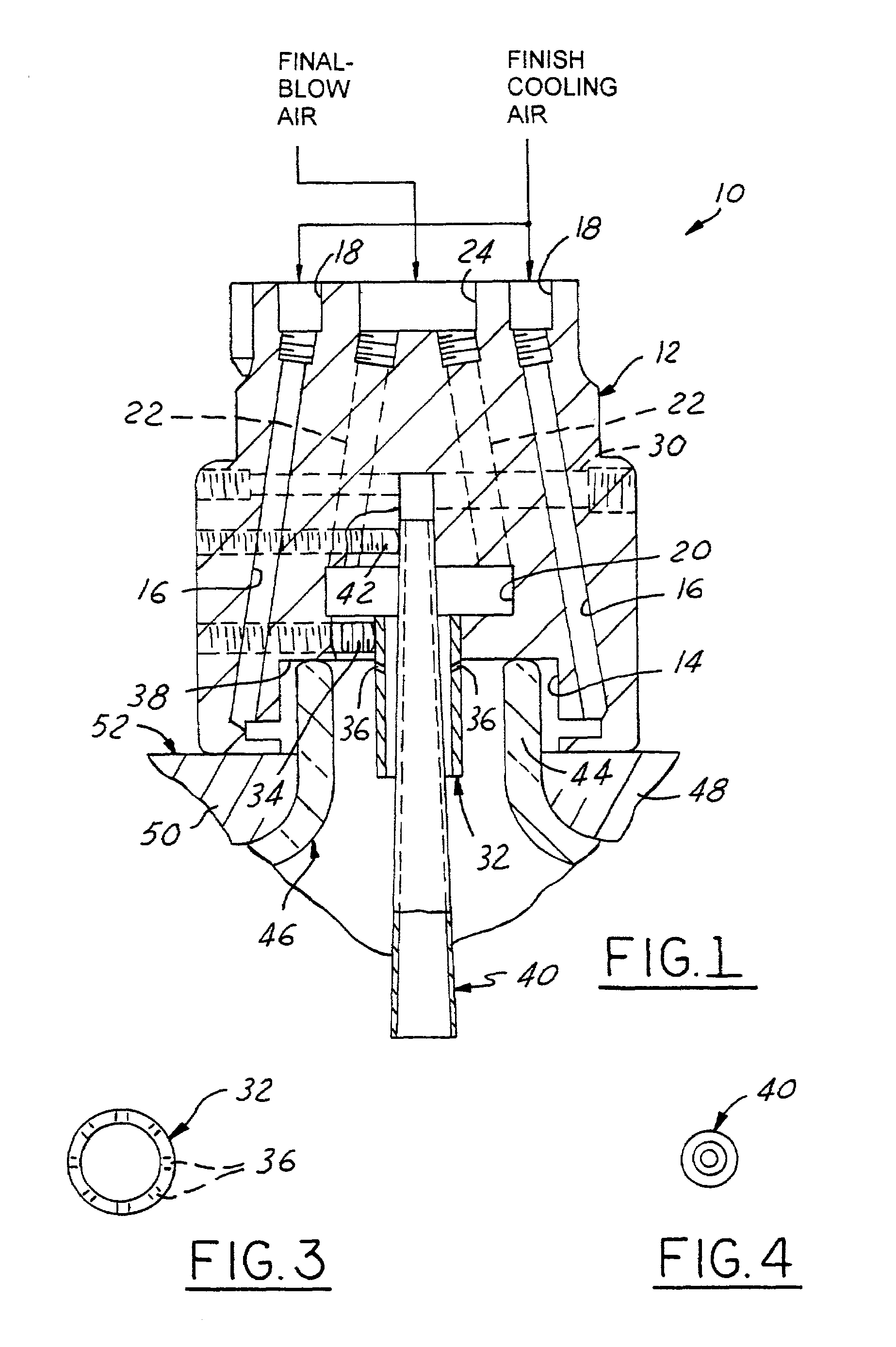
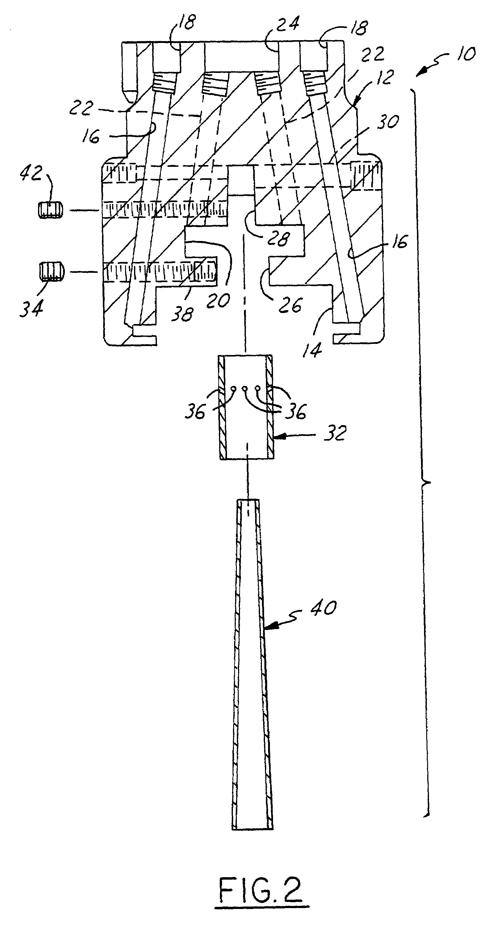
[0010]FIGS. 1 and 2 illustrate a dual-stage blowhead assembly 10, sometimes referred to as an isolated finish blowhead assembly, in accordance with one presently preferred embodiment of the invention. Blowhead assembly 10 includes a blowhead body 12 having a first chamber 14 that opens at one end of the blowhead body. At least one first passage 16, and preferably a plurality of first passages 16 extend to chamber 14 from a first inlet 18 at the opposing end of body 12. Passages 16 are disposed in a circumferential array around the central axis of body 12. A second chamber 20 is disposed within body 12 at a position axially spaced from and preferably coaxial with chamber 14. At least one second passage 22, and preferably a circumferential array of second passages 22 extend to the periphery of chamber 20 from a second inlet 24 at the opposing end of the blowhead body. A cylindrical passage 26 extends coaxially from chamber 20 to chamber 14. A passage 28 extends from the opposing or in...


PUM

PropertyMeasurementUnit
angleaaaaaaaaaa
taper angleaaaaaaaaaa
diametersaaaaaaaaaa

Abstract

A blowhead assembly for receipt over a parison finish to blow the parison within a blow mold and simultaneously cool the parison finish includes a blowhead body having a first chamber at one end for receipt over the finish of a parison in a blow mold, and at least one passage in the blowhead extending to the chamber from a first inlet for directing cooling air onto the external surface of a parison finish in the chamber. A second chamber in the blowhead body is spaced from the first chamber, and at least one second passage in the blowhead body extends to the second chamber from a second inlet for directing blow air into the second chamber. A first tube extends from the second chamber through the first chamber for receipt within a parison finish in the first chamber to feed blow air from the second chamber into the parison. A second tube extends from an exhaust passage in the blowhead body through the second chamber and through the first tube for receiving exhaust air from the parison. The second tube is coaxial with the first tube and extends beyond the free end of the first tube. The second tube has at least a free end that flares radially outwardly for deflecting blow air from the first tube radially outwardly within the parison.

Description

[0001]The present invention relates to blowheads for blowing articles of glassware in blow molds of a glassware manufacturing machine, and more particularly to a dual-stage blowhead assembly with finish external and internal cooling capability.BACKGROUND AND SUMMARY OF THE INVENTION[0002]Glassware, such as glass bottles, is typically made in a so-called individual section machine, which includes a plurality of identical sections that operate out of phase with each other to produce the glassware. Each section includes one or more blank or parison molds, in which gobs of molten glass are either pressed or blown to form blanks or parisons. Each parison is then removed from the blank mold and placed in a final-blow mold. A blowhead is lowered over the parison in the blow mold, and final-blow air is directed into the parison through the blowhead to form the parison against the internal surface of the final-blow mold. The blown articles of glassware are then removed from the molds.[0003]C...

Claims


Application Information

Patent Timeline
Patent Type & Authority Patents(United States)
IPC IPC(8): C03B9/00C03B9/325C03B9/36C03B9/38
CPCC03B9/325C03B9/3672C03B9/385
Inventor DODD, MARK P.
Owner OWENS-BROCKWAY GLASS CONTAINER INC
Why Eureka
Try Eureka