Advanced tool systems

Inactive Publication Date: 2005-08-02
BOUNCING BRAIN INNOVATIONS SUBSIDIARY 3 LLC
View PDF51 Cites 43 Cited by
  • Summary
  • Abstract
  • Description
  • Claims
  • Application Information

AI Technical Summary

Benefits of technology

[0032]This invention is an economical, yet versatile tool and system which provides increased access and effici

Problems solved by technology

The drive adaptor may be eliminated by incorporating it as part of formed tube, however this will limit it's versatility to function with other drive adaptors for other uses.

Method used


Image

  • Advanced tool systems
  • Advanced tool systems
  • Advanced tool systems

Examples


Embodiment Construction

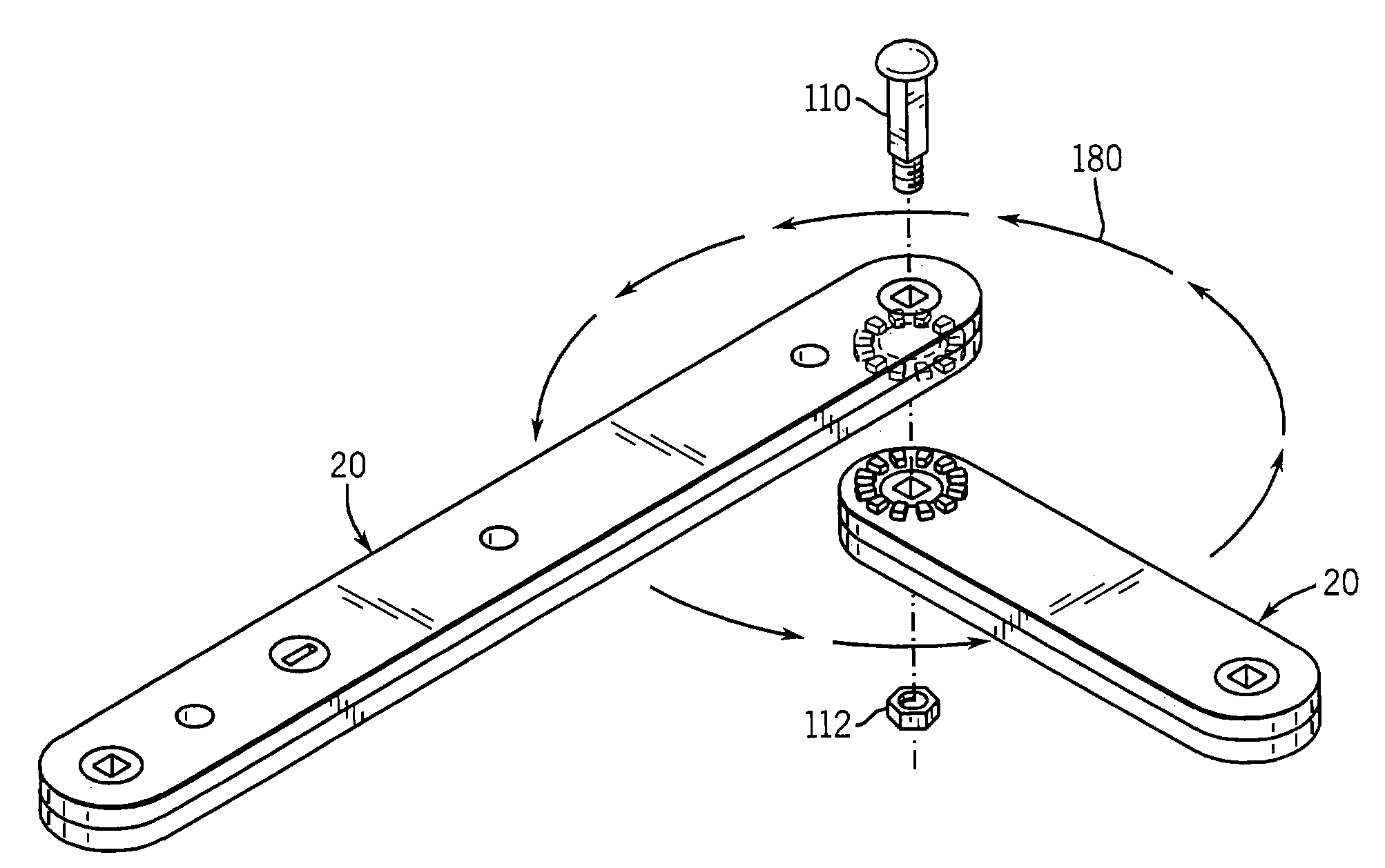
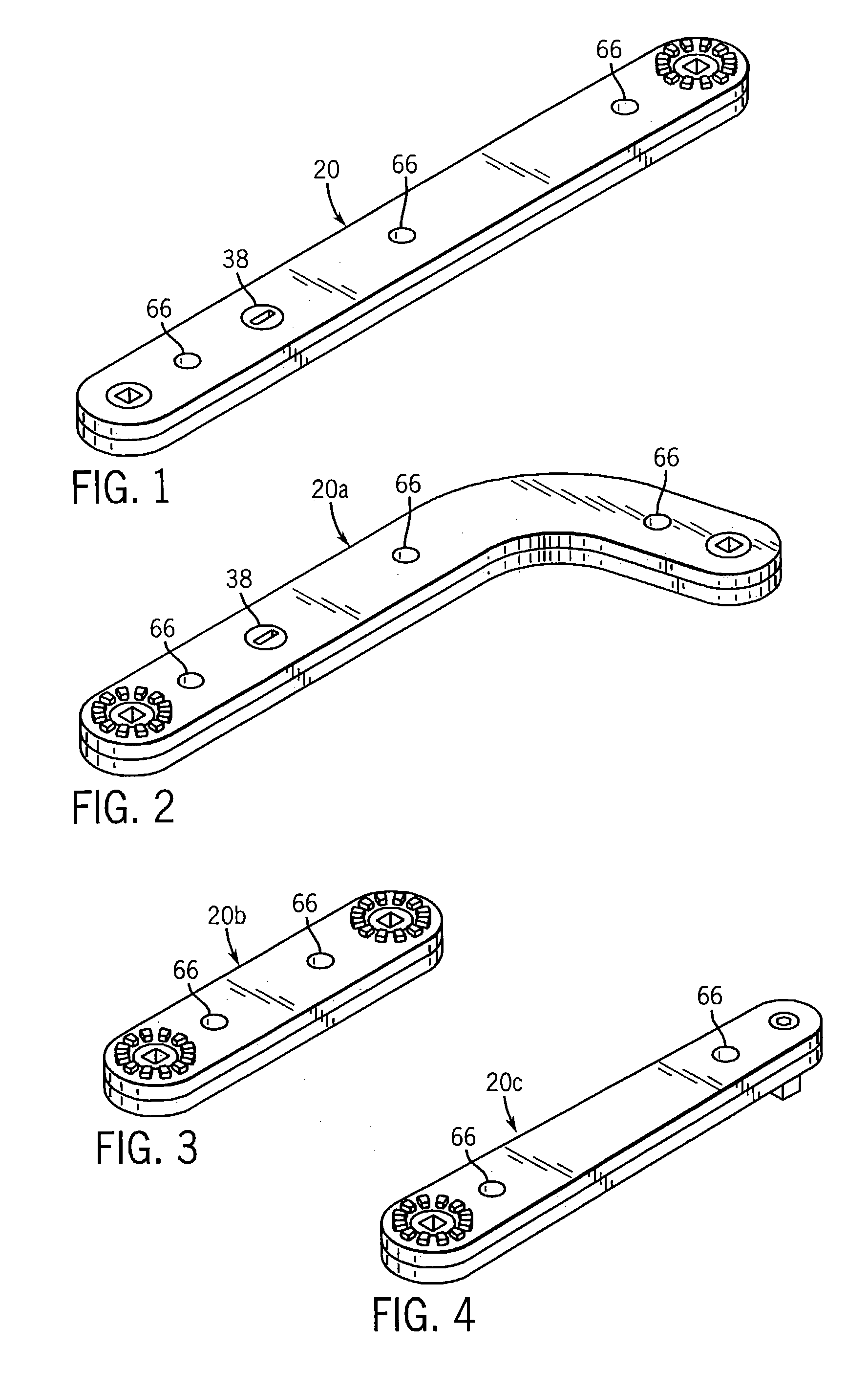
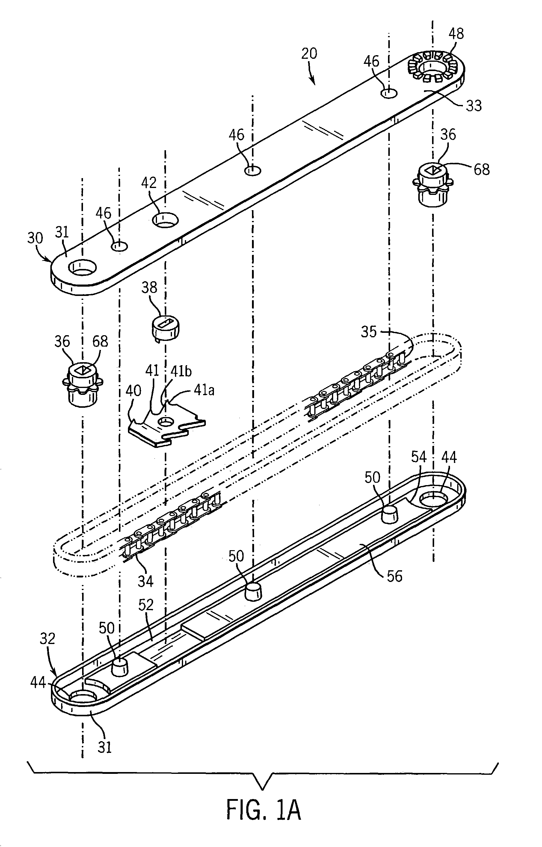
[0136]A preferred embodiment of a chain drive tool 20 of the present invention is shown in FIGS. 1 and 1A. The tool 20 provides an outer housing comprised of a top 30 and a bottom 32 housing to enclose or contain the preferred flexible drive mechanism that includes an endless element which preferably is a roller chain 34 encircling two rotatable elements in the form of sprockets 36. Sprockets 36 are rotatably drivable one by the other via chain 34 and can receive and transmit rotational forces via preferred internal square drive receptacles or other configurations located axially therein or any other desired connectors (not shown).

[0137]The housing top and bottom 30, 32 and other components are preferably cast such as by die casting, or molded from precision dies to control working distance between sprocket bearing holes 44 for mounting the sprockets 36 for rotation in the housing at an input end 31 and an output end 33. Close tolerance chain tracks 56 or other suitable channels pro...


PUM


Abstract

A tool has a pair of elongate housings adapted to be joined together in a housing assembly for enclosing and supporting a flexible drive mechanism entrained about a pair of rotatable elements. Each of the rotatable elements is disposed on the housing assembly at opposite ends thereof. A flexible drive mechanism provides a transfer of power between the rotatable elements so that rotation of one rotatable element at one input end of the housing assembly will effect driven rotation of the other rotatable element at an output end of the housing assembly. The elongate housings include male and female configurations for aligning and joining the housings without independent fasteners.

Description

CROSS-REFERENCE TO RELATED APPLICATIONS[0001]This application is a division of application Ser. No. 10 / 034,902 filed Dec. 27, 2001, now U.S. Pat. No. 6,647,830, which claims benefit of Provisional U.S. Patent Application No. 60 / 259,065 filed Dec. 29, 2000.FIELD OF THE INVENTION[0002]This invention relates generally to tools with a rotational power output providing distance extending, angle changing, torque increasing and rotational power transferring capabilities. More particularly, the invention relates to chain drive tools and a system which provides an improved, simplified rotational power transferring capability with a directional control or ratcheting option and a modular option that allows assembling the tools in a wide variety of angular and extended configurations to enable accomplishing tasks such as tightening and loosening threaded fasteners and the like located in remote, difficult to reach or limited access locations. The present invention has further utility in the fie...

Claims


Application Information

Patent Timeline
IPC IPC(8): B23Q5/00B25B13/00B25B13/48B25B13/46B23Q5/04B25B21/00B25B17/00B25F5/00
CPCB23Q5/045B23Q5/048B25B13/467B25B13/481B25B17/00B25B21/002B25F5/001
Inventor MARQUARDT, STEVEN H.
Owner BOUNCING BRAIN INNOVATIONS SUBSIDIARY 3 LLC
Why Eureka
Try Eureka