Boatlift buoyancy system

Inactive Publication Date: 2005-08-02
ROSS JAY +1
View PDF7 Cites 11 Cited by
  • Summary
  • Abstract
  • Description
  • Claims
  • Application Information

AI Technical Summary

Benefits of technology

[0017]An additional object is to provide a boatlift buoyancy system that significantly decreases the effective weigh

Problems solved by technology

Boatlifts can exceed 600 pounds and are very difficult to maneuver even when positioned in deep water.
While these devices may be suitable for the particular purpose to which they address, they are not

Method used


Image

  • Boatlift buoyancy system
  • Boatlift buoyancy system
  • Boatlift buoyancy system

Examples


Embodiment Construction

A. Overview

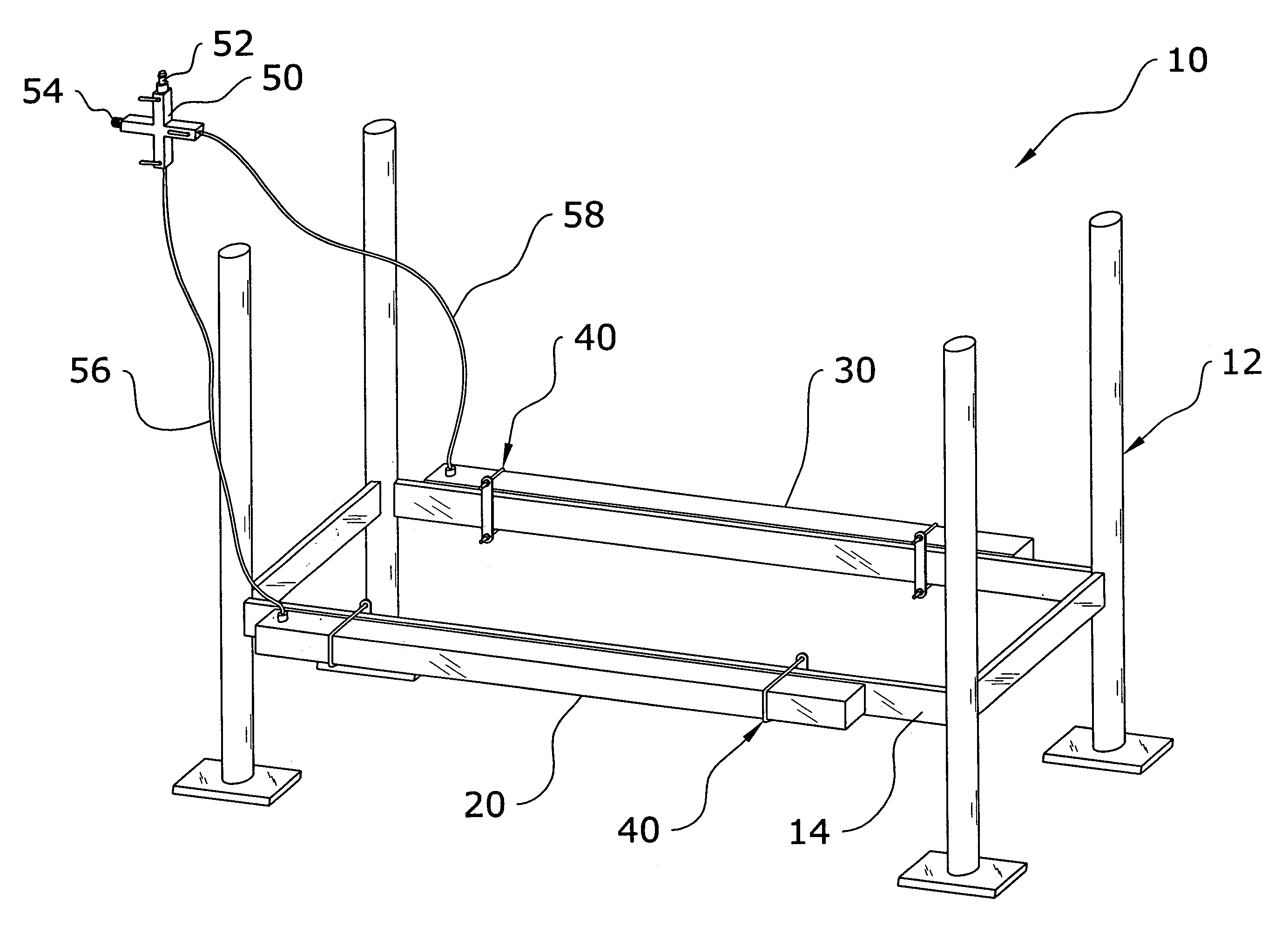
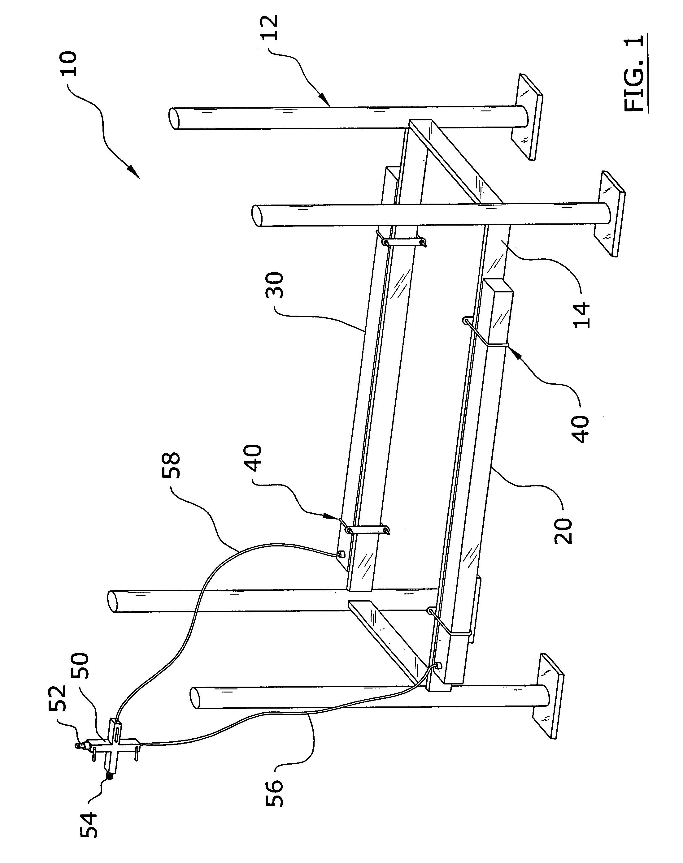
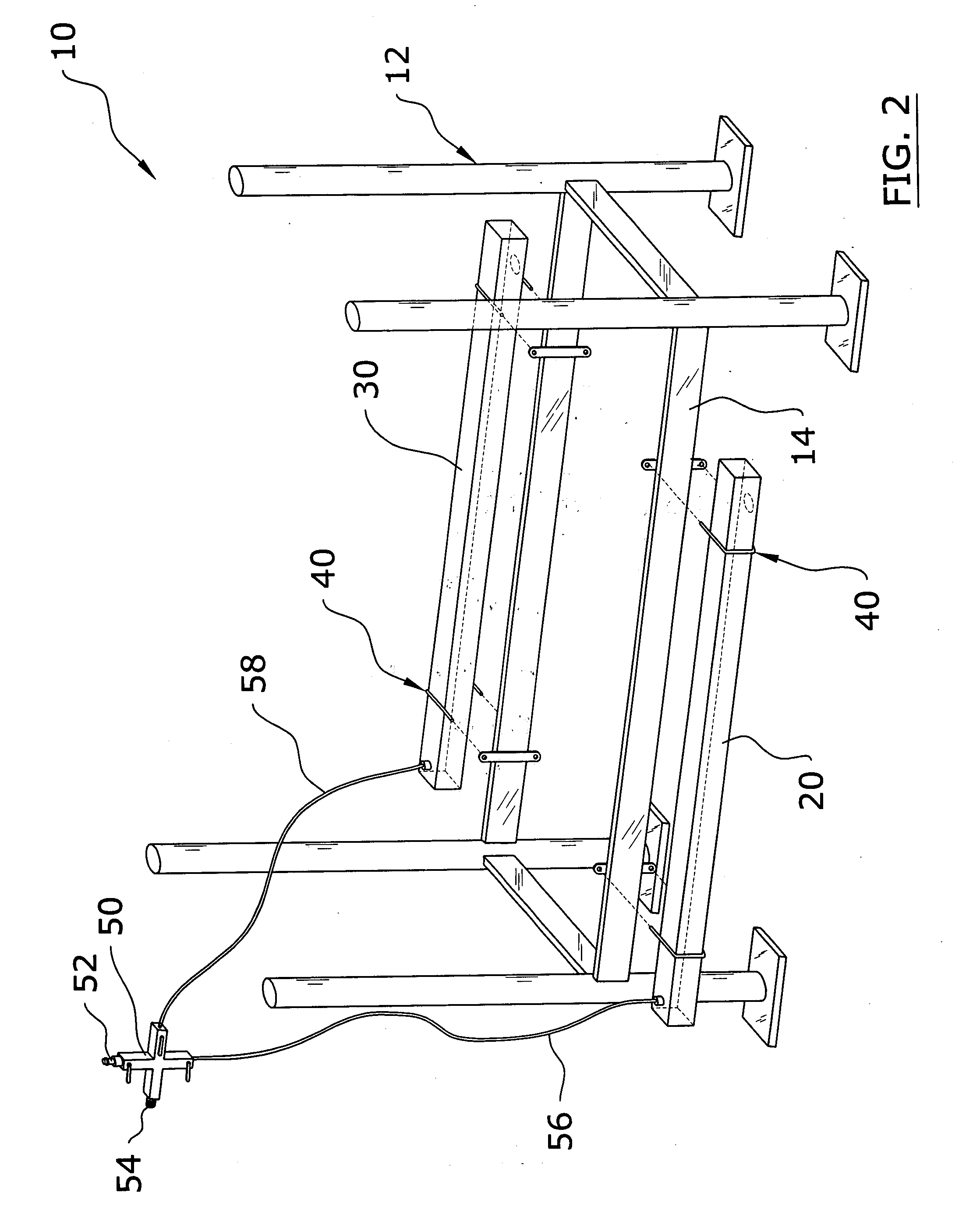
[0031]Turning now descriptively to the drawings, in which similar reference characters denote similar elements throughout the several views, FIGS. 1 through 8 illustrate a boatlift buoyancy system 10, which comprises a first tube 20 and a second tube 30 attachable to the horizontal support beams 14 of a boatlift 12 that are capable of receiving of volume of air and / or water. A first hose 56 and a second hose 58 are fluidly connected to the first tube 20 and second tube 30 respectively for delivering pressurized air when buoyancy is desired for the boatlift 12. The first tube 20 and the second tube 30 also have a first aperture 22 and a second aperture 32 respectively within lower portions thereof for allowing for the draining of water when pressurized air is input into the 20, 30.

B. Buoyancy Tubes

[0032]The first tube 20 and the second tube 30 each have a tubular structure having an interior cavity. The first tube 20 and the second tube 30 are preferably removably attachab...


PUM


Abstract

A boatlift buoyancy system for assisting in maneuvering a boatlift while in the water by adding buoyancy to the boatlift. The boatlift buoyancy system includes a first tube and a second tube attachable to the horizontal support beams of a boatlift that are capable of receiving of volume of air and/or water. A first hose and a second hose are fluidly connected to the first tube and second tube respectively for delivering pressurized air when buoyancy is desired for the boatlift. The first tube and the second tube also have a first aperture and a second aperture respectively within lower portions thereof for allowing for the draining of water when pressurized air is input into the tubes.

Description

CROSS REFERENCE TO RELATED APPLICATIONS[0001]Not applicable to this application.STATEMENT REGARDING FEDERALLY SPONSORED RESEARCH OR DEVELOPMENT[0002]Not applicable to this application.BACKGROUND OF THE INVENTION[0003]1. Field of the Invention[0004]The present invention relates generally to boatlifts and more specifically it relates to a boatlift buoyancy system for assisting in maneuvering a boatlift while in the water by adding buoyancy to the boatlift.[0005]2. Description of the Related Art[0006]Boatlifts have been in use for years for supporting boats during non-usage. FIG. 1 of the drawings illustrates an exemplary boatlift that the present invention may be utilized upon. Boatlifts are typically comprised of a tubular metal structure (e.g. aluminum, steel, etc.) and are relatively heavy. Boatlifts can exceed 600 pounds and are very difficult to maneuver even when positioned in deep water.[0007]While these devices may be suitable for the particular purpose to which they address, ...

Claims


Application Information

Patent Timeline
IPC IPC(8): B63C3/00B63C3/06
CPCB63C3/06
Inventor ROSS, JAYHENDRICKSON, LANCE
Owner ROSS JAY
Why Eureka
Try Eureka