Compressed air vehicle having enhanced performance through use of magnus effect

a technology of compressed air and magnus, which is applied in the field of compressed air vehicles having enhanced performance through use of magnus effect, can solve problems such as achieve the effects of reducing the effective weight of the system, improving the efficiency of compressed air vehicle systems, and reducing the effective weight of the tank during operation

Active Publication Date: 2012-01-19
GRACE WINSTON
View PDF2 Cites 3 Cited by
  • Summary
  • Abstract
  • Description
  • Claims
  • Application Information

AI Technical Summary

Benefits of technology

[0011]The present invention improves the efficiency of compressed air vehicle systems by adapting the compressed air storage tank with a Magnus rotor that creates lift so as to reduce the effective weight of the tank during operation. A compressed air tank has an outlet in fluid communication with the inlet of a compressed air motor. Air leaving the compressed air motor is caused to flow across the Magnus rotor whereby lift is generated to counter gravitational force thereby reducing the effective weight of the system. A battery powered electric fan has an inlet disposed to draw air across the Magnus rotor thereby increasing the velocity of the air so as to maximize the Magnus effect. A thermoelectric cooler transfers heat across the compressed air motor, i.e. from air exiting the compressed air motor outlet, to the air entering the compressed air motor inlet, whereby the temperature of the air entering the compressed air motor is increased resulting in increased pressure. Conversely, transferring heat from the air exiting the compressed air motor and prior to flowing across the Magnus rotor, increases the density of the air flowing across the Magnus rotor so as to maximize the efficiency of the Magnus effect. Finally, the fan has an output in fluid communication with the input of a compressor, which re-compresses the air and delivers the re-compressed air to the storage tank.
[0013]Another object of the present invention is to improve the efficiency of compressed air vehicles by harnessing the Magnus effect.
[0014]Still another object of the present invention is to improve the efficiency of a compressed air engine by heating the compressed air prior to introduction into the compressed air motor.

Problems solved by technology

Air leaving the compressed air motor is caused to flow across the Magnus rotor whereby lift is generated to counter gravitational force thereby reducing the effective weight of the system.

Method used


Image

  • Compressed air vehicle having enhanced performance through use of magnus effect
  • Compressed air vehicle having enhanced performance through use of magnus effect
  • Compressed air vehicle having enhanced performance through use of magnus effect

Examples


Embodiment Construction

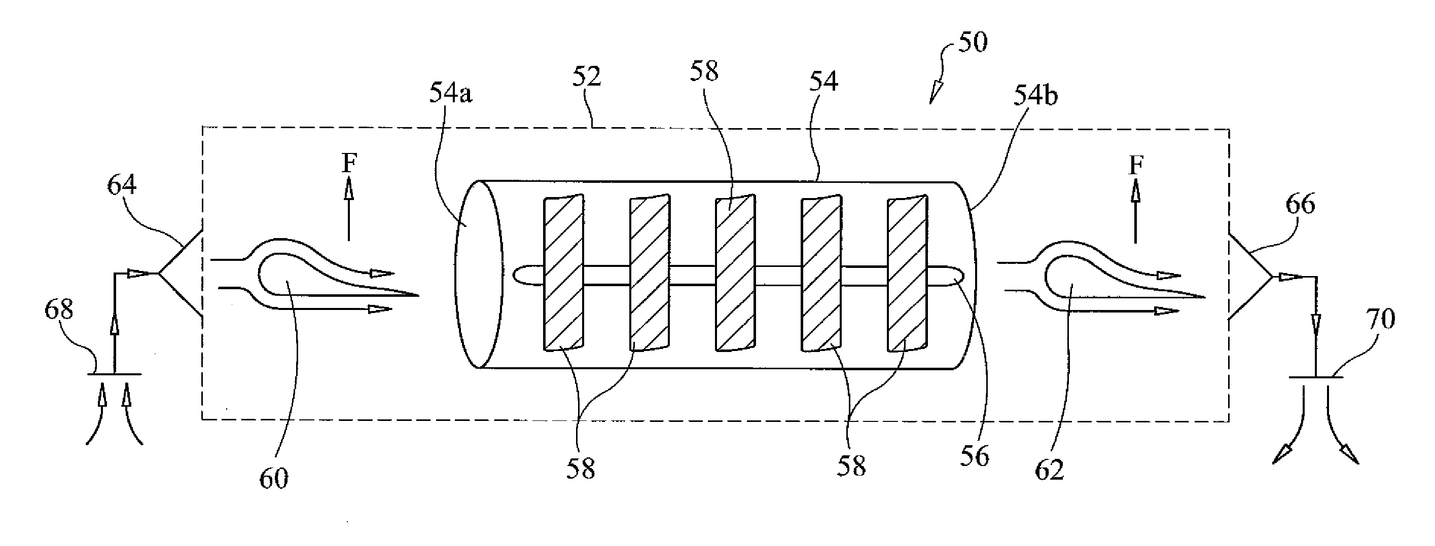
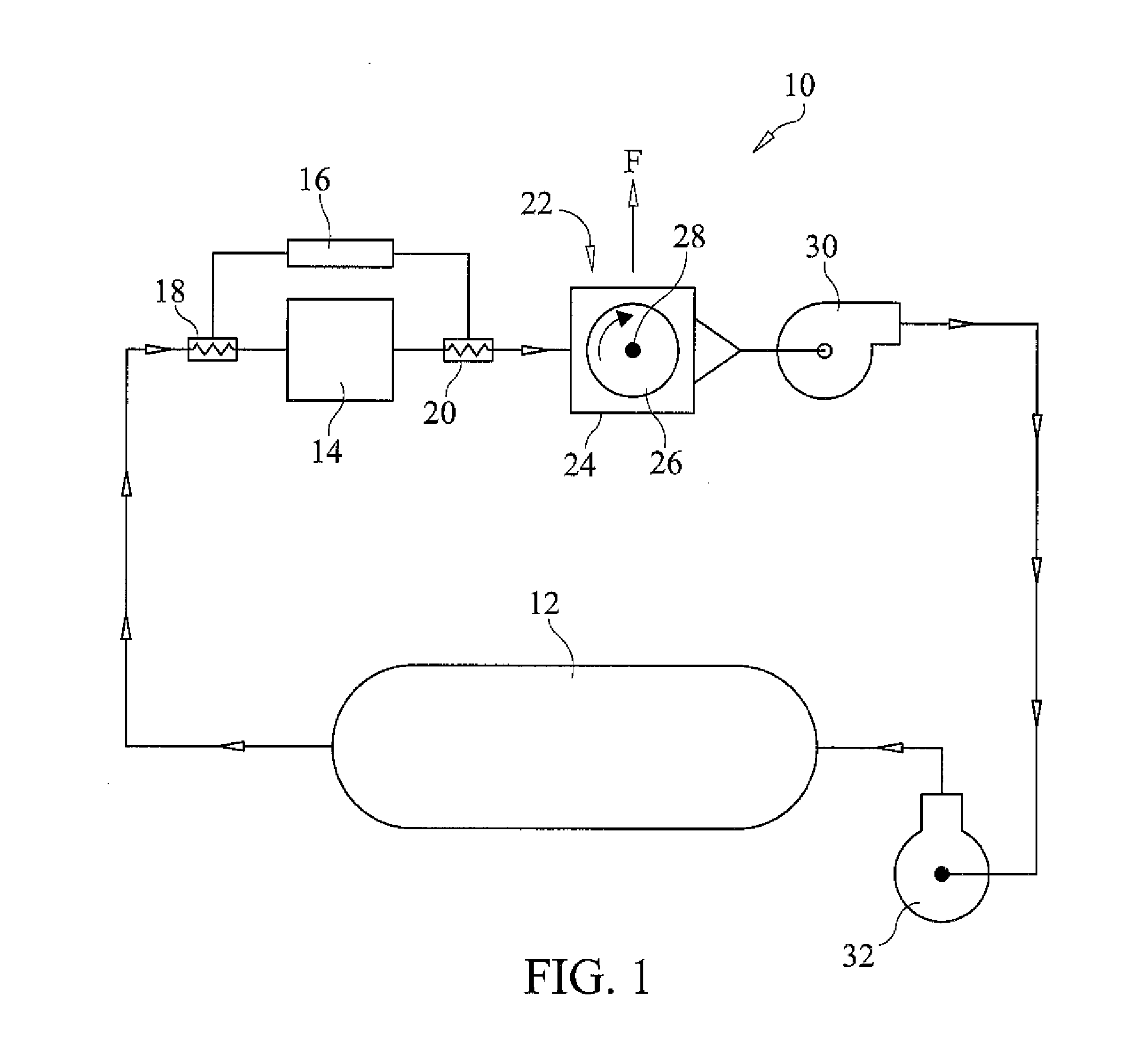
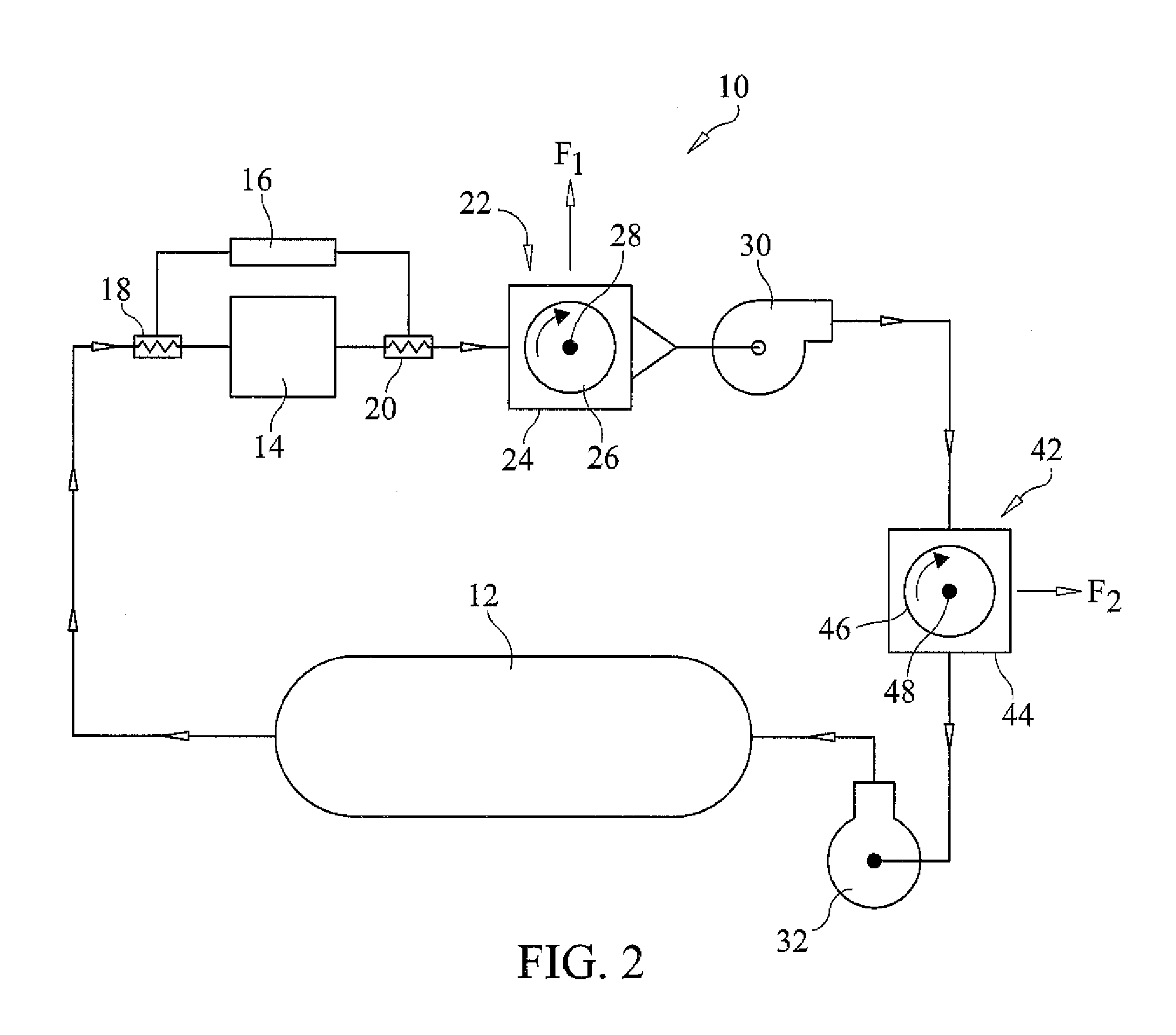
[0019]With reference now to the drawings, FIGS. 1-3 depict various embodiments of the present invention. FIG. 1 is a schematic illustration of a compressed air engine system, generally referenced as 10, for use in propelling a vehicle in accordance with the present invention. Efficiency of the compressed air vehicle is enhanced by adapting the compressed air storage tank with a Magnus rotor that creates lift so as to reduce the effective weight of the tank during operation as more fully discussed herein. A compressed air tank 12 has an outlet in fluid communication with the inlet of a compressed air motor 14 for routing high pressure air from tank 12 to motor 14. Compressed air motor 14 comprises a motor that produces power output using any suitable compressed fluid, preferably air.

[0020]A thermoelectric cooler 16 is connected to heat exchangers 18 and 20 disposed on the outlet and inlet sides respectively of compressed air motor 14 as illustrated in FIG. 1.

[0021]Thermoelectric cool...


PUM


Abstract

The efficiency of compressed air vehicle is enhanced by adapting the compressed air storage tank with a Magnus rotor that creates lift so as to reduce the effective weight of the tank during operation. A compressed air tank has an outlet in fluid communication with the inlet of a compressed air motor. Air leaving the compressed air motor is caused to flow across the Magnus rotor whereby lift is generated to counter gravitational force thereby reducing the effective weight of the system. A battery powered electric fan has an inlet disposed to draw air across the Magnus rotor thereby increasing the velocity of the air so as to maximize the Magnus effect. A thermoelectric cooler transfers heat across the compressed air motor, i.e. from air exiting the compressed air motor outlet, to the air entering the compressed air motor inlet, whereby the temperature of the air entering the compressed air motor is increased resulting in increased pressure. Conversely, transferring heat from the air exiting the compressed air motor and prior to flowing across the Magnus rotor, increases the density of the air flowing across the Magnus rotor so as to maximize the efficiency of the Magnus effect. Finally, the fan has an output in fluid communication with the input of a compressor, which re-compresses the air and delivers the re-compressed air to the storage tank.

Description

CROSS REFERENCE TO RELATED APPLICATIONS[0001]N / ASTATEMENT REGARDING FEDERALLY SPONSORED RESEARCH OR DEVELOPMENT[0002]N / ACOPYRIGHT NOTICE[0003]A portion of the disclosure of this patent document contains material that is subject to copyright protection. The copyright owner has no objection to the facsimile reproduction by anyone of the patent document or patent disclosure as it appears in the Patent and Trademark Office patent file or records, but otherwise reserves all copyrights rights whatsoever.BACKGROUND OF THE INVENTION[0004]1. Field of the Invention[0005]The present invention relates to vehicles that are propelled using a source of compressed gas, such as air, and more particularly, to a system and method for improving the efficiency of such vehicles by use of one or more Magnus rotors that reduce the weight of the vehicle and while facilitating compression of gas to charge the compressed air tank.[0006]2. Description of Related Art[0007]It is known in the art to use compresse...

Claims


Application Information

Patent Timeline
Patent Type & Authority Applications(United States)
IPC IPC(8): F01D15/02
CPCB60K15/03006B60K3/00
Inventor GRACE, WINSTON
Owner GRACE WINSTON
Why Eureka
Try Eureka