Snow plow having a pneumatic lifting device for reducing the wear on the blade of the snow plow

a technology of lifting device and snow plow, which is applied in the field of snow plows, can solve the problems of reducing the effective weight of the snow plow on the underlying surface and the raising and achieve the effect of reducing the effective weight of the snow plow

Active Publication Date: 2017-07-04
GODWIN JR JAMES PATRICK
View PDF16 Cites 3 Cited by
  • Summary
  • Abstract
  • Description
  • Claims
  • Application Information

AI Technical Summary

Benefits of technology

[0005]The present invention relates to a snow plow having associated therewith a pneumatic or compressed air control system for reducing the effective weight of the snow plow when the snow plow is disposed in a lower snow plowing position.
[0006]In one embodiment, the pneumatic control system includes an air bladder or air springs that is operatively connected to a source of compressed air. The air bladder is also operatively associated with a lift arm that is, in turn, operatively connected to the snow plow. By pressurizing the air bladder, the air bladder expands and raises the lift arm, which in turn exerts an upward force on the snow plow, reducing its effective weight on the underlying surface. This reduces friction generated between the lower edge of the blade of the snow plow and the underlying surface and substantially reduces the wear on the blade of the snow plow.
[0007]In one particular embodiment, the air bladder or air springs is sandwiched between a lower lift arm and an upper lift arm. The lower lift arm is connected to a hydraulic cylinder, while the upper lift arm is operatively connected to the snow plow. By actuating the hydraulic cylinder, the snow plow can be raised from a lower snow plowing position to a raised travel position. That is, the hydraulic cylinder causes the lower lift arm to raise, which in turn engages the upper lift arm which results in the snow plow being raised. When the snow plow is disposed in the lower snow plowing position, the pneumatic bladder is pressurized by a compressed air source and this causes the upper lift arm to raise relative to the lower lift arm. Because the upper lift arm is operatively connected to the snow plow, this means that the upward movement of the upper lift arm results in an upward force being exerted on the snow plow, which effectively reduces the weight of the snow plow on the underlying surface.

Problems solved by technology

By pressurizing the air bladder, the air bladder expands and raises the lift arm, which in turn exerts an upward force on the snow plow, reducing its effective weight on the underlying surface.
That is, the hydraulic cylinder causes the lower lift arm to raise, which in turn engages the upper lift arm which results in the snow plow being raised.

Method used


Image

  • Snow plow having a pneumatic lifting device for reducing the wear on the blade of the snow plow
  • Snow plow having a pneumatic lifting device for reducing the wear on the blade of the snow plow
  • Snow plow having a pneumatic lifting device for reducing the wear on the blade of the snow plow

Examples


Embodiment Construction

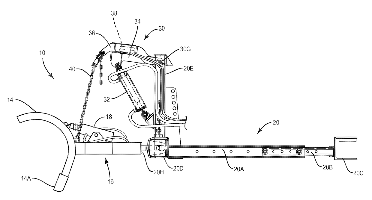
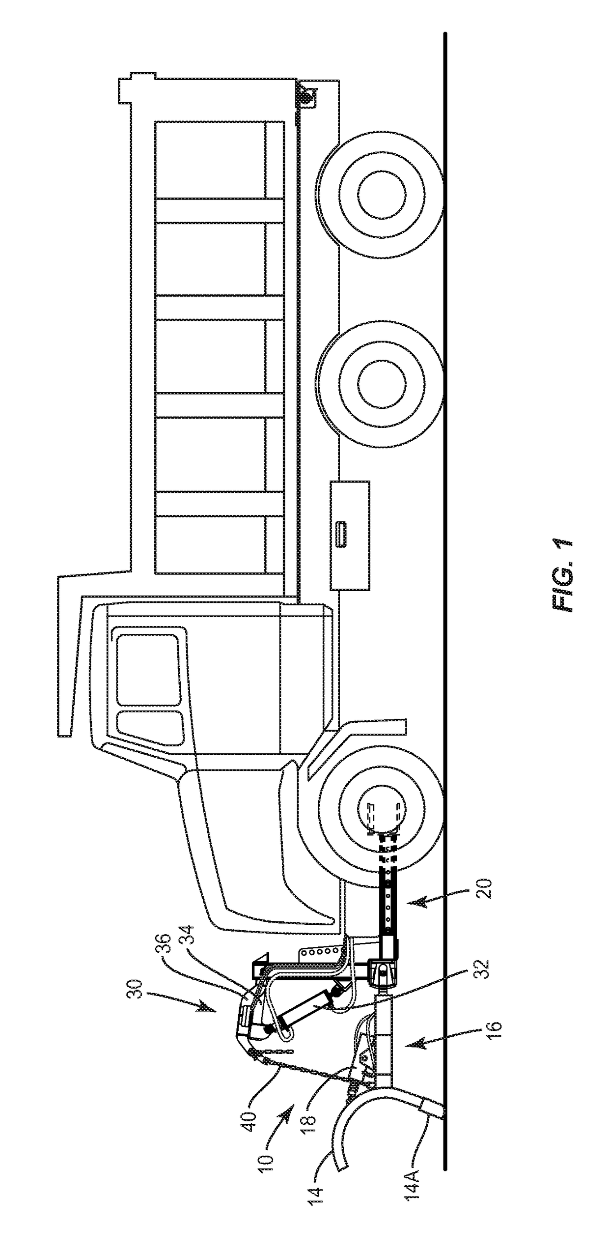
[0016]With further reference to the drawings, particularly FIG. 1, the snow plow of the present invention is shown therein and indicated generally by the numeral 10. Snow plow 10 is secured to a truck 12 and projects forwardly therefrom. Snow plow 10 can assume various designs. An exemplary snow plow design is shown in the drawings, but it is understood and appreciated that the present invention can be incorporated and used in virtually all snow plow designs. Thus, a detailed description of the snow plow 10 is not dealt with herein because such snow plow designs are well known and appreciated by those skilled in the art. However, an overview of the snow plow 10 is presented. Snow plow 10 includes a blade 14 and a blade carrier frame indicated generally by the numeral 16. Blade 14 typically includes a moldboard with stiffeners. In addition, blade 14 includes a lower blade or cutting blade 14A that in operation typically engages an underlying surface such as a roadway. Also, in many c...


PUM


Abstract

A snow plow lifting device is operatively connected to a snow plow for selectively imparting a lifting force on the snow plow. This lifting force reduces the effective weight of the snow plow bearing on an underlying surface such as a roadway. Thus, during a snow plowing operation, this reduces the wear on a lower edge of a blade that forms a part of the snow plow.

Description

FIELD OF THE INVENTION[0001]The present invention relates to snow plows.BACKGROUND OF THE INVENTION[0002]Snow plows include a blade that generally comprises a moldboard and, in many instances, a lower trip board is formed across the lower edge of the moldboard. The snow plow is pivotally connected to a push frame that is mounted to a vehicle or to another type of prime mover. A hydraulic cylinder and lift arm are typically operatively interconnected between the push frame and the snow plow. This allows the snow plow to be moved back and forth between a lower snow plowing position and a raised travel position.[0003]Snow plows are typically heavy. When the lift arm is fully lowered, the trip board or the lower edge of the blade engages and rests on an underlying surface such as a roadway. Now the full weight of the snow plow is supported by the underlying surface. When the plow is operated in this state, there is typically a rapid wear on the trip board or the lower edge of the blade....

Claims


Application Information

Patent Timeline
Patent Type & Authority Patents(United States)
IPC IPC(8): E01H5/06
CPCE01H5/061E01H5/06E01H5/063
Inventor GODWIN, JR., JAMES PATRICK
Owner GODWIN JR JAMES PATRICK
Why Eureka
Try Eureka